Yes please!
Very interested too! ![]()
Sounds good. I am in for one.
if you could make 17mm version, i’m IN
So... I made a whole bunch of improvements to the GXB20 V1..
I just received the news PCBs for it... introducing the new GXB20 V2! 
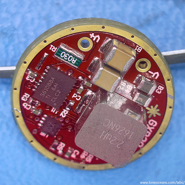
Still writing the (improved) firmware with a lot more additional and optional functionality, this time with 3 extra mode selection jumpers or E-switch control. And a complete layout redesign, on-board programming connection which will hopefully be a lot easier to use, and improved power electronics.
More to come soon! :)
V2 looks nice!
WOW very professionally built. Great looking with plenty of retaining ring clearance.
Different components used? Besides layout, any hardware changes that I can take when I eventually get around to building the previous versions I have?
Hello, yes there were some slight changes in the feedback and digital potentiometer allowing for more variations in brightness. I also conducted some experiments in the power section but I don't think there are any hardware changes needed to be made so far (some changes I made resulted in same or slightly less efficient results so the original is good enough :) )
Another quick update and thanks again to everyone who's been following this project!
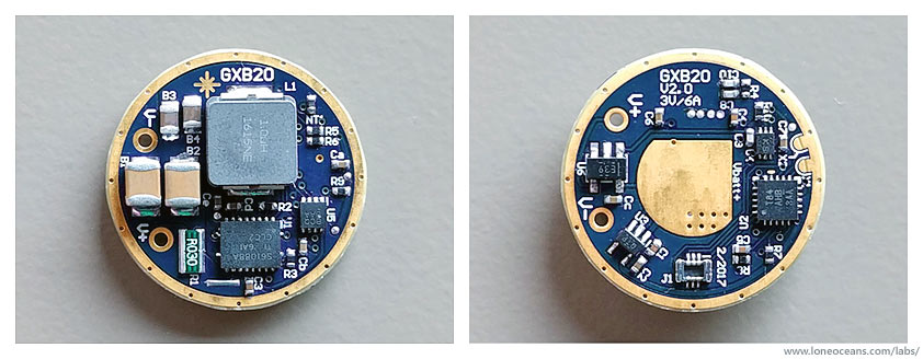
GXB20 Version 2
In short, the changes I've made for the V2 version turned out to be an improvement over the original by a small amount, and after a little more testing I think I'm happy with the result for now, and the GXB20 driver has achieved all the goals I had set out at the beginning of the project!
By no means is this a complete nor 'commercial' driver, which will certainly require a little more optimization and better firmware, but I think I'm quite happy with how it is as-is, for a hobby project. Currently I'm working on finishing a more complete write-up on this driver, and will be publishing everything open-source for all to use and to fabricate boards (e.g. from OSHpark).
Some notes on the additional improvements of the GXB20 V2:
- Better placement and layout (I hope!)
- Much more levels of constant current brightness (256, adjustable using 1 resistor)
- Improved lowest level of CC brightness (just around 1mA - true 'firefly' mode)
- Modes for my own firmware: 1 = firefly <1mA, 2 = low ~180mA, 3 = mid ~600mA, 4 = ~1.8A (~1000 lumens), 5 = 3A (turbo)
- Measured efficiency of 92% at 3A (~6.5V) output
- Two new solder-bridge mode jumpers + extra GPIO for easy mode selections
- (needs more firmware work to take advantage of all of these)
- New 0.4mm pitch micro programming header for ATtiny84A
- Works better at lower voltages when approaching 2.5V
- + maintains all the features of the original GXB20 V1
I did some experiments in the power section but it turns out that they didn't make too much of a difference (e.g. in the previous post you can see I used a bigger inductor but didn't see much benefit). The final improvement I'd probably want to do with this driver is to fabricate using half-thickness (0.8mm) PCB and 2oz copper, and of course continual work on the firmware to improve things further like adding more modes and improving EEPROM performance using a random hopping scheme.
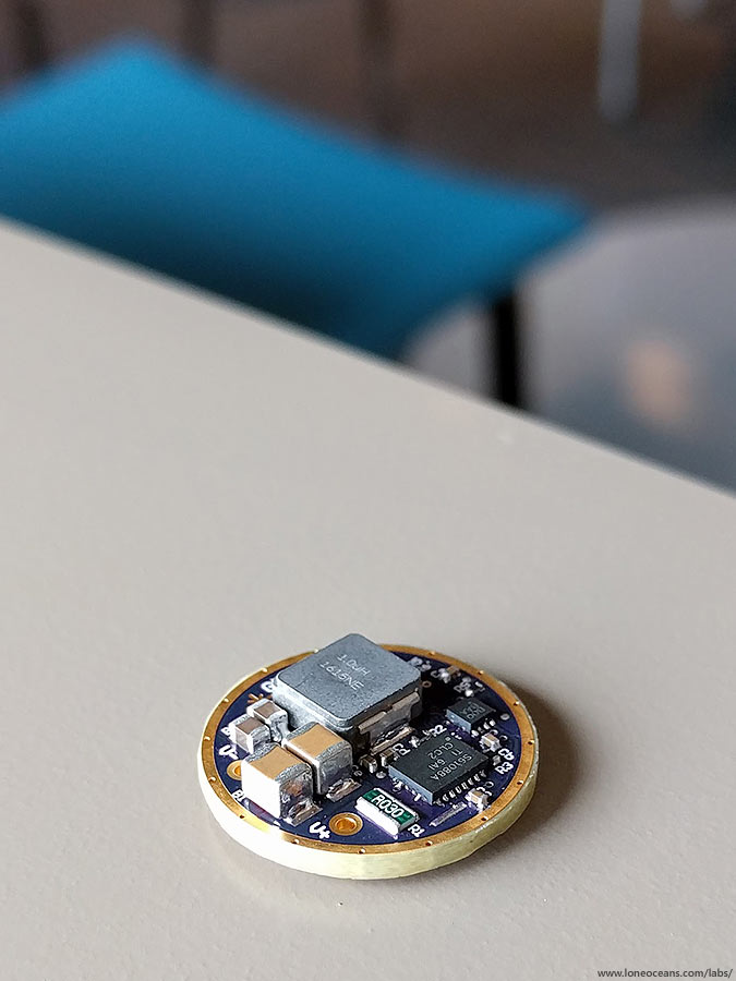
Finally, above is another view of the GXB20 V2 driver.
Looking good :+1:
Good news! This is a pretty cool result for a hobby project!
That looks so neat. :+1:
The side picture gives another perspective to the difference in height size of the components.
Were you able to hit the 95% efficiency goal? Remarkable work here.
I see that the top says GXB20 V2.0 3V/6A. Is this a typo 3V/6A? What final voltage, amperage, efficiency did you get? And finally thanks for helping us out on getting a good single cell driver for these newer XHP LED’s.
Nice work! It’s a beautiful driver!
Ah >< I was hoping nobody would notice the typo  , but yep it was a mistake in the silkscreen - it's supposed to be 6V 3A. But I think I can claim that the nominal input power is ~3+V at 6A, so that's still ok :).
The efficiency numbers are roughly the same as the chart that I posted earlier. Again efficiency varies depending on the input supply and the load, but realistically the converter should have a total efficiency ranging from ~85 to 95%. This is the total converter efficiency, with some additional loss in the current sense resistor. Maximum I've tested for the GXB20 topology is the same as the previous with a measured 3.8V in at 6.32A, and an LED current of 3.26A at ~88% efficiency.
However for the GXB20v2, I've measured a total converter efficiency of 92% with an input of 21.39W at 6.01A and output of 19.76W at 3.0A. I'm also pleased to say that the lowest possible brightness I got with the GXB20v2 is really low at an LED voltage of 4.52V and around 1mA, so it's a true moonlight, or more like fire-fly mode :). I have yet to fabricate a PCB with thicker copper (2oz) which will improve things a little more.
Regardless, as I've found, at such high power levels, just basic DC resistance plays a huge role in efficiency especially with low single-cell voltages. In practical aspects, I found it very challenging to avoid significant voltage drop at over 6A (at least with the cheap flashlight host I'm using), which I suppose places a practical limitation in how much more power I can push through. Any more and the voltage the driver sees becomes a little low, and overall efficiency also drops.
I know this is a bit off topic, but how would this boost driver with a 4500mah 26650 compare to a linear driver of the same 3 amps, but using a pair of 2200mah 26350 batteries?
Would voltage sag be about the same under the same load?
Is efficiency a lot less?
I know there’s a big difference in 18mm batteries because name brand 18650 are much higher mah than small brand 18350. But with 26mm there doesn’t seem to be the big difference.
Nice!
I wonder if it’s possible to get a smaller design with lower power. Like 17mm 9V/1A for 219C triple.
Low power buck drivers are already available.