They’re bright and comes in 9080! No tint shift so far.
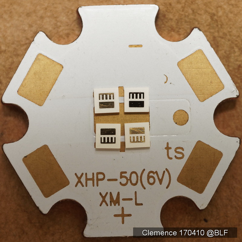
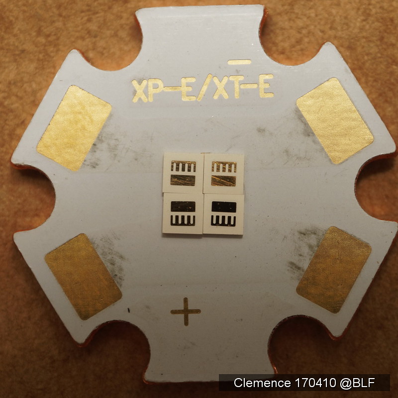
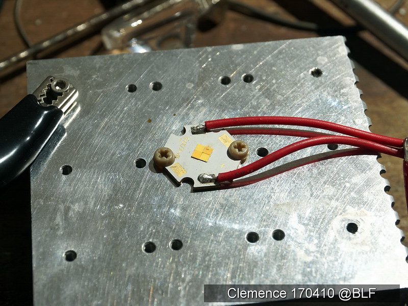
With XP sinkpad you get oval beam, 2p E21A non isolated, with XM sinkpad you get 4p E21A non isolated. Cathode must be soldered to the MCPCB’s thermal pad. Scrap the masking paint between pads for best result (minimal solder thickness). Also to get the most flat arrays.
Any non conductive thermal pad will do. Best with thin thermal grease on an anodized heatsink.
Yes, 4x 17A should exactly fit an (DTP) XP-pad, all minusses (cathodes) soldered on the thermal pad. The body has become led-minus, a minor problem to solve :party:
And with this one we can get the almost impossible to get: 9080 4500K Nichia
I’ll post my result with 2pcs sm503 and 2 pcs sm303 on a XM DTP board later
It seems there are two ways to deal with the lack of a thermal pad. One way is just to electrically isolate the MCPCB from the flashlight body. As clemence suggested, an anodized shelf with thermal grease should isolate fine, but most shelves are not anodized. Another simple way to electrically isolate the MCPCB is to put a layer of kapton tape around the perimeter of the MCPCB so there is no metal-to-metal contact, then fill the space between shelf and star with thermal paste. Kapton tape is 25-50 microns thick and thermal paste has at least 2 W/mK thermal conductivity, so with a 16mm MCPCB the thermal resistance of the thermal paste is 0.25-0.5 K/W, which is pretty small. Anyway, there are lots of solutions to the problem, but this is the one I was thinking of using.
The other way, as djozz is suggesting, is to electrically connect the flashlight body to the (+) or (-) of the LEDs. I read your description of how to have the LED positive connected to the body, but how would you deal with having the LED negative connected to the body? Putting the driver in the tailcap is one way…
With DTP XM MCPCB it will create a funny beam
Will be a trending topic with DTP XP MCPCB
My suggestion is to use DTP aluminum XP MCPCB, then anodize the back side. Easy and straighforward application with existing host.
This will be a very nice 3 Volt class 4,2mm quad die!! With the possibility for tint mixing and individual control.
- Clemence
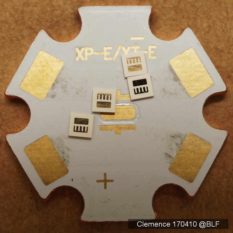
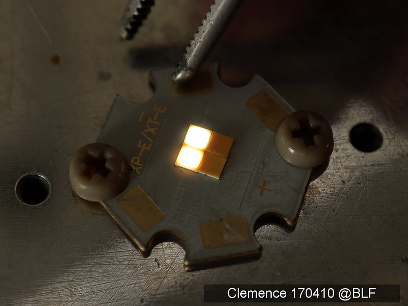
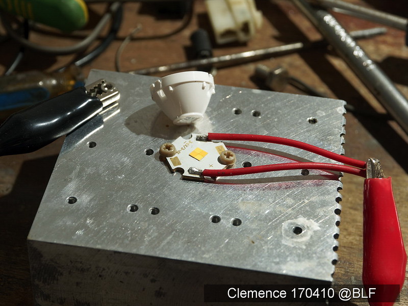
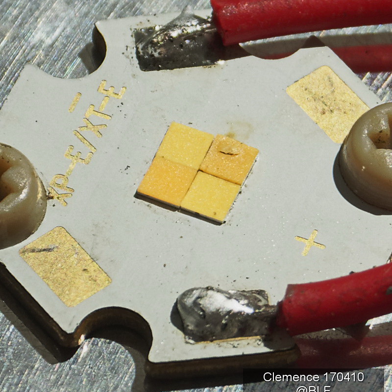
Eventhough the thermal pad isn't enough for all LEDs to sit on, I gave them a try...
Please don't complain about it, they're tiny, harder to handle, and fly easily. The sm303 9080 is thicker by 0,1mm. Let's see how Djozz handle the smaller E17A later.
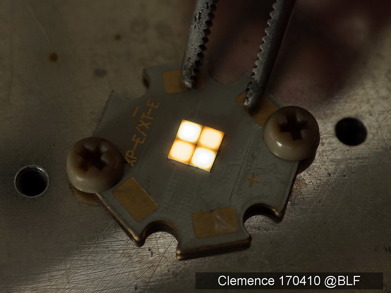
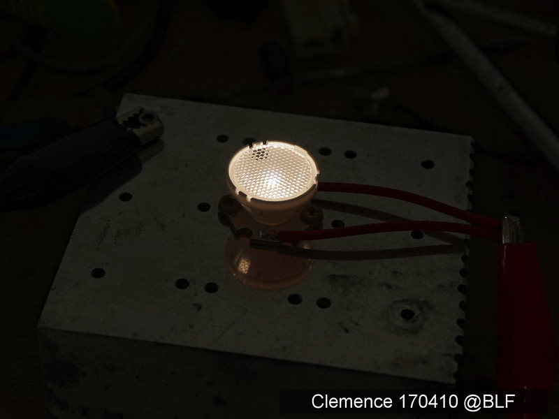
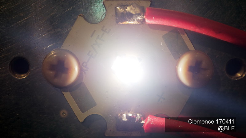
ultra low current by multimeter could lit them all
Could be Windows next logo
Gaps, yes I know...
Fits aliexpress XML optics loosely
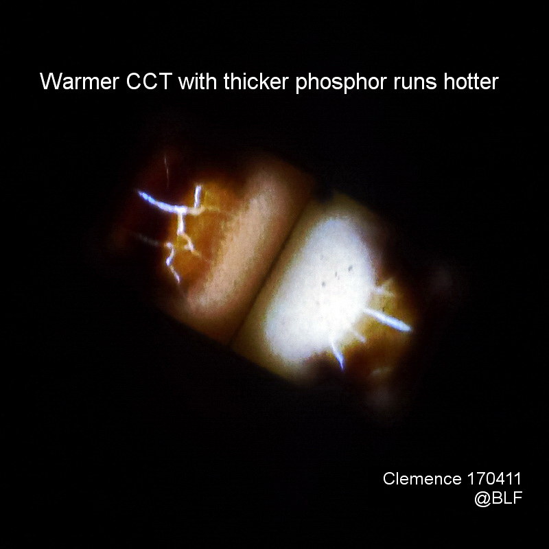
Pleasant 4500K
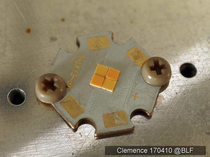
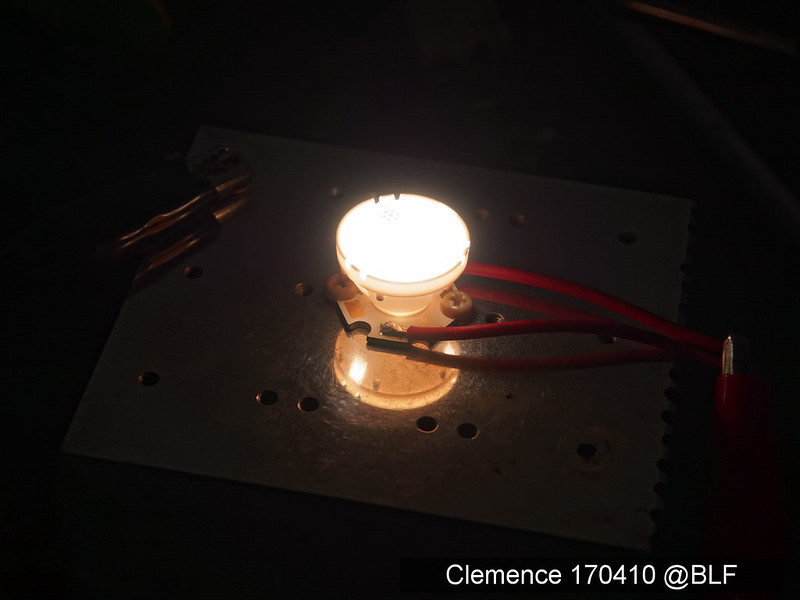
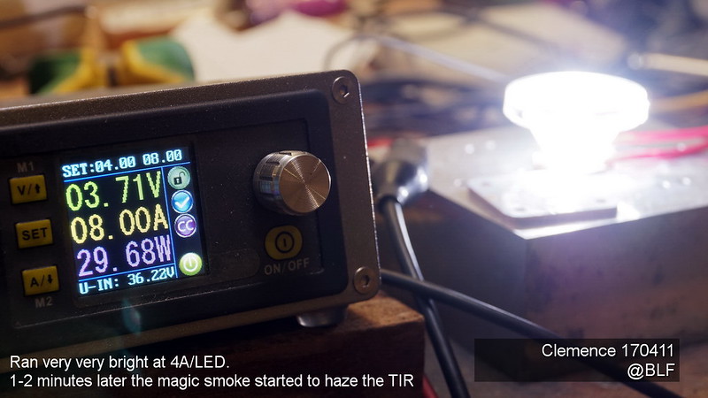
And....pffffffftttt! one dead at 4,6A. With proper MCPCB these should handle up to 8A
The burns damage all through the MCPCB and short the whole array. Three survived, I'll keep them for later test
Thanks for the nice tests! Pity about the burnt led. At 4.6A that is just 1.15A per led (well, ‘just’ as in the usual BLF expectations). Let’s hope that it handles more current when better mounted.
And that was using the 20mm XP DTP MCPCB with the largest thermal pad. Sinkpad XP has much smaller thermal pad. I guess your E17A will fit better in XP MCPCB
Very interesting test, not sure why I want not subscribed to this thread.
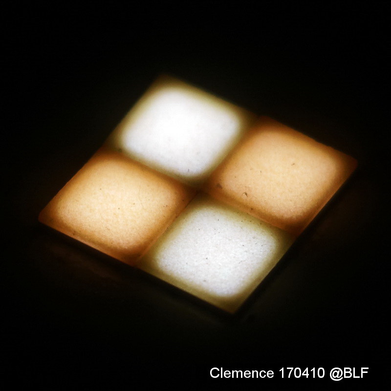
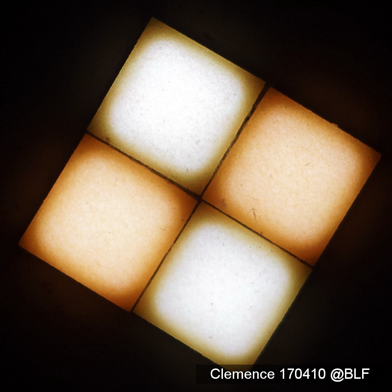
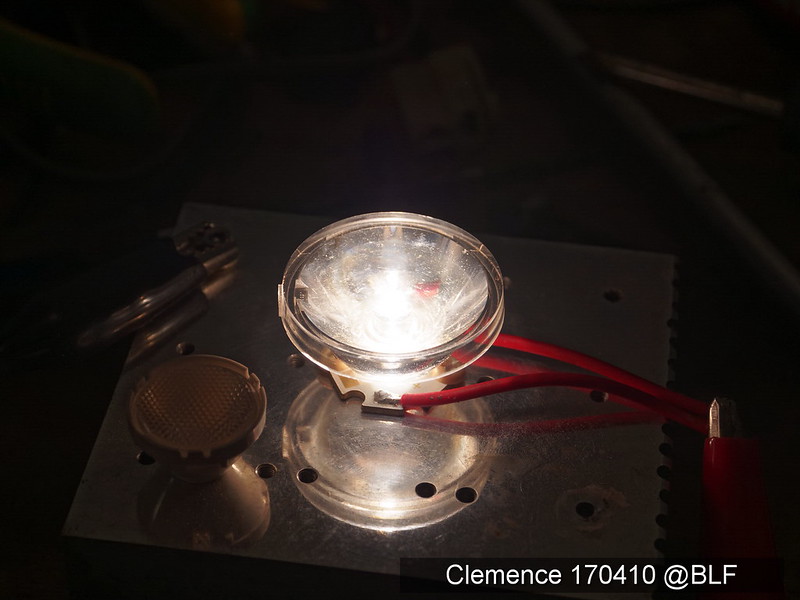
Thanks for the test. That is disappointing; the die doesn’t actually extend to the edge of the package, making it impossible to create a gapless quad.
The gap would be so small as to be unnoticeable in an actual light except for maybe a zoomie I bet.
I am more confused at the early death of the LED myself. Even before the datasheet limits.
The gap looks to be at least as large as in the XHP70, though it will probably be less noticeable because of the phosphor covering, sort of like the XHP50.2. But whether or not you see a donut hole in the beam, gaps reduce the peak beam lux in a reflector light.
Looks way smaller then an XHP70 to my eye, got to remember that this is a 3535 footprint they are sitting on, the xhp70 sits on a 7070 footprint, twice the size.
To me it looks lighter packed then an xhp50. In fact it would not be hard to figure out, if clemence can measure the total size of the dies we can compare that to the total size of the xhp50 dies.
The E21A package width is 2.1mm, so similar to the XHP70 individual die size. Estimating from measuring images:

The width of the gap between the dies in the XHP70 is about 7% of one die width. For the E21A quad pictured above, it is about 13%, even taking into account the small gap between the packages. So there is comparatively more dim/unlit area in the E21A quad.
FYI, those picture taken with ultra low current from my multimeter. And I haven’t use silicone to bridge the air gaps in between tiles to reduce photon crossing losses.
Nice testing clemence. The gaps must of been so small that its not untill you take a macro shot that they appear large. :+1:
What I had not hoped for with the 17A and 21A: the actual die under the phosfor is clearly smaller than the full dimension of the led, thus the fading edges. That will not be solved by filling the gaps with silicone. A quad led set-up will face the same challenges that the first gen. XHP leds (and the old MC-E and MK-R) have: no smooth reflector for this quad!
Silicone will reduce phosphor surface temperature by reducing the photons bounced back and accumulates heat on the phosphor surface. Each time the photons hit air gap, they will bounced back unless in straight line. I didn’t mention it to cure the cross mark.
FYI, they survived 8A (for a minute or two). Still editing the pictures
- Clemence
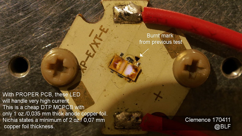
Well that looks a bit more promising. The picture really shows which parts need better heat sinking. Do you know if noctigon XP16/20 MCPCBs use 2oz copper thickness? It seems like the area/layout of the copper on the MCPCB could make a big difference, too. On noctigon stars the trace from the pos and neg contact is the width of the footprint (3.5mm). On the other hand, on this 20mm TPAD I have in front of me the trace is thinner and there is a bottle neck of 1mm right at the footprint; not as good for heat transfer. Ideally the trace would spread out and cover as much area as possible to increase the heat transfer across the insulating layer to the metal below, just like the Nichia 119 MCPCB that djozz designed.