I’d love to be able to buy the charging boards that JKK uses. I could have sworn I’ve seen it for sale before, but I haven’t been able to find them again for years.
Hello,
I think i got the wrong parts delivered. They arrived some time ago but i did not had the time to use them and i did not check them when they arrived. I ordered SKU:S006044 (21mm Parallel Star for CREE MC-E (5PCS)) and i got 5 MCPCB that are Serial if i am not wrong

Cool boards! But serial indeed :cry:
Nice boards indeed! And the LED would fit perfectly if it were a single color MC-E. But i have 8 RGBW MC-Es left and i have (after checking) not 5 but 10 Serial boards. I ordered 2x 5 Parallel. Hope they have enough Parallel boards left. To mod the boards so that i can make it work would be possible but to do it 8 times is a pain in the ass! And i do not know if i could still use these optics (http://www.mouser.de/Search/ProductDetail.aspx?R=CA10945_RGBX-MC-Ovirtualkey56980000virtualkey928-CA10945RMCO) if i mod the boards (do not know if i have enough space for the wires to go directly to the pins of the LED).


On a side note, Jensen567 recently did some research on the H1-A driver. Here's my pertaining feedback:
Based on a TPS61088 integrated boost converter plus PIC 12F683 microcontroller, in stock configuration output voltage is capped to ≈7.3+V via a resistor divider located next to the stock current sense resistor (R025, 25mΩ). Jensen567 found that, if we change the resistor just to the left of the inductor, northeast from the current sensing one, we can increase the maximum output voltage of the driver. Please note that, from the chip's datasheet, maximum Vout won't go above 12.6V (unsuitable for 4S emitters), and also the fact that the maximum input current for the TPS61088 is 10A, so after efficiency losses bear in mind you shouldn't gamble much above 25W of total output power, if at all. This, however, means we can use this driver to power in series triples. Please, increase the current sense resistor value to reduce the output current if wishing to go triple in series setup. Sense voltage is 75mV: with an R030 (30mΩ), output current is 2.5A; with an R050 + R100 stacked (33.3͡ mΩ), output is at 2.25A.
Oh! The resistor to replace is surrounded by a green circle in the following picture:
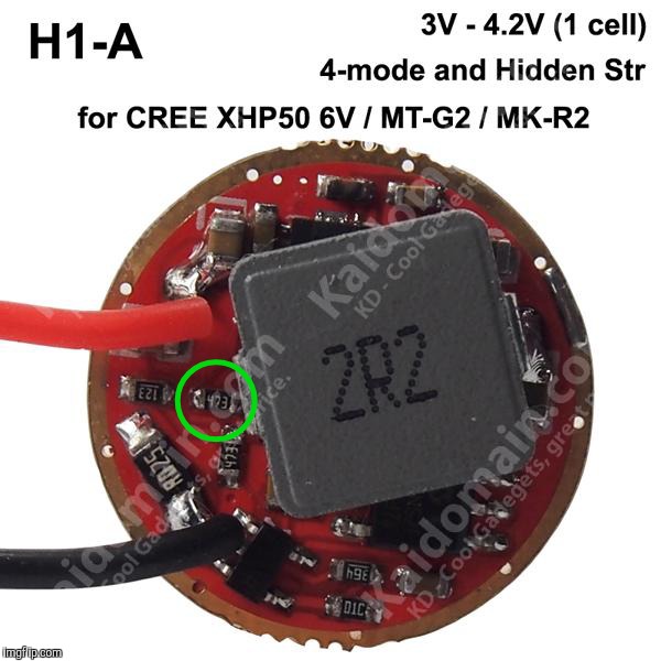
Jensen567 measured 10.72V open circuit voltage for a 75KΩ resistor in place of the 47KΩ stock one. This is adequate for 3S arrangement. I bet an 82KΩ would also work nicely, allowing slightly more Vout if needed, but this is untested.
Enjoy!
Cheers ^:)
…
Thanks for pursuing this, finding drivers for triple serial layouts is at best a confusing problem (for me)
Having never built a triple series light… why would one go that route?
mattlward, versus a FET hack reference, thIs in series boost driver provides:
- Less maximum peak output, we already know that. Our main limitation here is the maximum allowable input current to the driver (10A theoretical) and its efficiency, which rule the amount of power burned in the driver. However, up to ≈25W of output is nice enough for a lot of 1S setups, really enough power to make a compact torch hot fast.
- Fully regulated modes, no pulse-width-modulation dung, constant output within battery voltage/SoC window.
- Full battery utilization (down to 3V) with shutdown. In my opinion, we should make aware the developers of these drivers they should use slightly lower cutoff values for high current input drivers, as any little stray resistance can become a serious input burden.
A tailcap FET switch may be advisable.

I want to say thanks. The Problem is solved! KD :+1: ![]()
If anybody can use 1-10 MC-E Serial boards let me know. I do not want money for the boards only shipping costs.
But i think it is only interisting for people from the EU because of the shipping costs.
Hi BanL,
What is the best driver for this particular led? Which is also available in Kaidoman.
Thanks
Too many variables to give an answer without knowing your needed driver size and cell configuration Erwin18.
will the led get damaged with this board : http://www.kaidomain.com/p/S026840.Osram-SFH-4716AS-IR850nm-IR-Emitter-with-KDLIGHT-3535-20-20mm-x-1_5mm-DTP-Copper-MCPCB ? isnt the center pad positive+ ?
this will be nice project http://www.kaidomain.com/p/S026829.Triple-Cree-XP-E2-Red-Green-Blue-LED-Emitter-with-20mm-x-1_5mm-DTP-Copper-PCB-Individual-w-optics + http://www.kaidomain.com/p/S026866.KZ-3016-Individual-Triple-LED-20mm-1_5A-2_7V-4_5V-Driver-Circuit-Board (wish the driver was 17mm and had 4th mode all leds on.)
Thank you for your understanding.
Thank you
You can let me know what is the driver size that you want to have?
And what is your battery configuration?
We have several drivers that is suitable for the CREE XHP35 LED.
You can refer for the search result
http://www.kaidomain.com/Search/SearchResult.XHP35/226
Thank you
Ban
Instead of pushing one LED to maximum possible brightness (at lower efficiency), or to mix several color temperatures (white) or colors (e.g. far red, red, and red-orange)
@BanL
Today i checked switches on your side. You have a nice assortment, but most of the time i am missing the information if it is a forward clicky or a reverse clicky switch. And that is something that a potentional buyer needs to know if he want that the driver and switch are working together.
Luminus SST-40 at Kaidomain, nice new possibility Ban! N4 is not the highest output bin, but I ordered two for testing!
http://www.kaidomain.com/p/S026881.Luminus-SST-40-N4-BA-White-6500K-LED-Emitter

is this code active?
Compared with xml2 how it performs?
Will other tint bins be available? I have one of these in a light already and they seem ok.