In this case, The inducator led works still?
and
LVP is set by R1/R2?
In this case, The inducator led works still?
and
LVP is set by R1/R2?
If the driver is wired to put the indicator LEDs behind the Zener/LDO, or the indicator LEDs otherwise have the right voltage going to them, I’d expect it to still work on a 2S/3S/4S build. They might need somewhat different resistor values though, in either case, to compensate for higher voltage.
About a Cheat Sheet for Narsil M,
lock here New BLF GT Narsil M Cheat Sheet for v1.2 NEW VERSION
Maybe somebody find it usefull.
I got a weird problem with NarsilM when the FET is limited to 90%
the ramping table is edited to be 230 max and also the mode sets
is there another aproach like reducing the ramp size or so?
but when the stepdown occurs it goes to 100% in first step down
same with ramping like 0.1, 1, 5%,10, 20…., 80, 90, 100, 90
I found a bug in Triple channel buil
the Indicator LED is not working, djozz reported it and I can confirm it
must be maybe the pinout settings are not right or some line of code wrong
channel.h forFET+1 build
channel.h for triple build
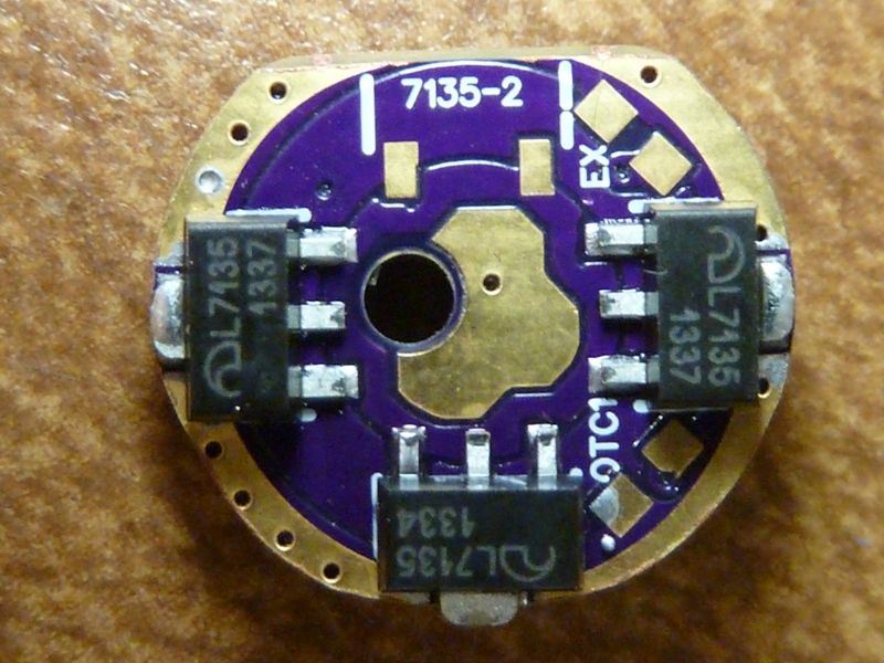
I'm pretty sure I got triple channel NarsilM 1.0 working fine with a Ind. LED. I have it installed now, from June 1st or so, in an OTR M3. It's got the delayed dbl-click, all the features of NarsilM 1.0 and uses TA's triple with 3 7135's as the bank:
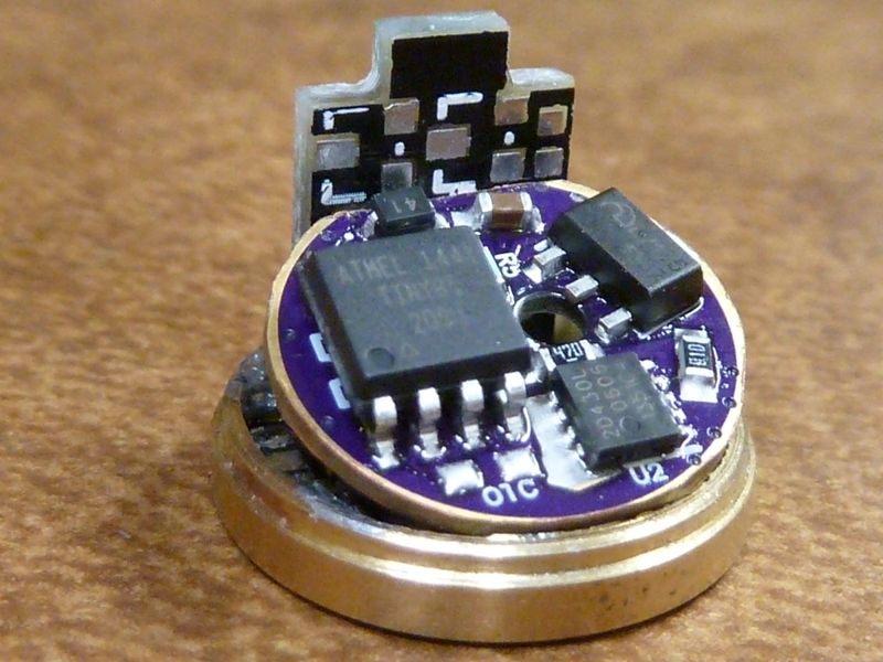
Link to NarsilM v1.0 folder with the special Setups-OTR M3.h header file: https://drive.google.com/open?id=0B1IxYZuk4DjcQWhOOGhTMExCNjg
You cant use external R1/R2 if you have the Indicator LED enabled. Works fine for me.
Hhmm - is the stepdown in mode sets? Is this still a problem? I'm gonna be working on this feature for the BLF GT, at least add the option into NarsilM. Plan on setting a max of like 80-90% for ramping, but still allow the dbl-click turbo to go to 100%.
It looks like you are talking bout mode sets, not ramping. Sounds like you didn't configure it correctly, but not sure. Think I already had a factory set of modes that didn't go to max output and I recall it worked fine.
Even with the setting file you gave me I got the same problem the indicator LED does not light up when it should
I get some light up of it,
but not as it should be,
the blinks which indicate which bank is active, voltage read out and standby does not work
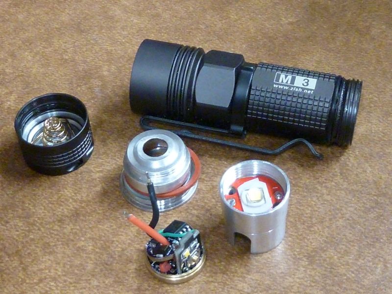
It’s rather impressive seeing all that in such a small host.
If you were so inclined, you could probably sell those for twice as much as the Olight S1 (S10?) it’s cloned from. Not sure that would be enough to make it worth your time, but it sure would be nice if there was a BLF light with the form factor of a S10/S1/S-Mini.
It was a challenge for sure. Sanding down the driver PCB was the most time consuming part. It is amazing though - same basic driver/design in a 37K lumens 16X XHP50 light, and the tiny OTR M3. I carry the M3 in the little pocket inside the regular jeans right hand pocket - no scratches, feels fine, no accidental ON's, don't have to lock it out.
All the pics here on the M3: http://s1054.photobucket.com/user/TomE2012/library/Custom%20Mods/OnTheRoad%20M3
All the pics here on the 16X S88 clone, 37K lumens monster: http://s1054.photobucket.com/user/TomE2012/library/Custom%20Mods/16X%20S88%20clone
Hmm? I haven’t noticed any problems with the indicator led either. But maybe I don’t know how it is actually supposed to work and therefor I’m thinking its working. What can I test to see if mine acts as yours or if it is really working?
I have high hopes for this one. I have it on the way. It’s hard to believe it has all the features for the price! And I’m thinking the space inside the head is going to limit the use of custom driver? Just think, add USB charger to that board Tom made :person_facepalming:
My M3 definitely works, been checking it. If all those things don't work, what does work? Does anything work with the Ind. LED?
I'm thinking maybe you got the default config settings set to disable the Ind. LED function, maybe?
These settings should be as follows:
I have not disabled the indicator LED in setup, I even activated it in the UI settings again
I have downloaded the narsil files from your google drive again
put in the OTR M3 setup
build a hex file and flashed it
the LED blinks when I push the button sometimes,
but it does not blink out voltage ot is active when the light is off
Ok. Mine works with battery voltage so pretty sure mine is working too. I’m using narsilM though…
The first I tryed the indicator did not work but then I read through setup, .c and all the included files to make sure the settings were right. However I do not recall what setting I changed in fact I don’t think I even knew what I did different. Sorry this doesn’t help you much though…
Can you upload your NarsilM folder somewhere?
Lexel:I have not disabled the indicator LED in setup, I even activated it in the UI settings again
I have downloaded the narsil files from your google drive again
put in the OTR M3 setup
build a hex file and flashed it
the LED blinks when I push the button sometimes,
but it does not blink out voltage ot is active when the light is offOk. Mine works with battery voltage so pretty sure mine is working too. I’m using narsilM though…
The first I tryed the indicator did not work but then I read through setup, .c and all the included files to make sure the settings were right. However I do not recall what setting I changed in fact I don’t think I even knew what I did different. Sorry this doesn’t help you much though…
/
* Setups.h
*
*
* Created: 4/30/2017 9:27:32 AM
* Author: Tom E
/
#ifndef SETTINGS_H_
#define SETTINGS_H_//————————————————————————————————————————————
// Driver Board Settings
//————————————————————————————————————————————
#define OUT_CHANNELS 3 // define the output channels as 1, 2 or 3#define VOLTAGE_MON // Comment out to disable - ramp down and eventual shutoff when battery is low
//#define VOLT_MON_R1R2 // uses external R1/R2 voltage divider, comment out for 1.1V internal ref// For voltage monitoring on pin #7, only uncomment one of the two def’s below:
//#define USING_220K // for using the 220K resistor
//#define USING_360K // for using a 360K resistor (LDO and 2S cells)#define D1_DIODE 4 // Drop over rev. polarity protection diode: 0.2V normally, 0.3V for Q8
// For 2 channel (FET+1) boards:
//#define USING_3807135_BANK // (default OFF) sets up ramping for 380 mA 7135’s instead of a FET// For 3 channel (triple) boards:
#define TRIPLE_3_7135 // Configure for 3 7135’s
//#define TRIPLE_8_7135 // Configure for 8 7135’s#define ONBOARD_LED // Enable the LED support
//————————————————————————————————————————————
//————————————————————————————————————————————//————————————————————————————————————————————
// Temperature Monitoring
//————————————————————————————————————————————
// Temperature Calibration Offset -
#define TEMP_CAL_OFFSET (–19)
// –19 For the OTR M3 (15 mm TA triple), –22 might be closer/better
// –2 try for the Manker U21 (LJ)
// –2 works for the Warsun X60 (robo) using the 17 mm DEL driver
// –1 try this for proto #1, OSHPark BLF Q8 driver
// 3 about right for BLF Q8 proto #2 and #3, reads ~20 for ~68F (18C)
// –12 this is about right on the DEL DDm-L4 board in the UranusFire C818 light
// –11 On the TA22 board in SupFire M2-Z, it’s bout 11-12C too high,reads 35C at room temp, 23C=73.4F
//8 For the Manker U11at –11, reads 18C at 71F room temp (22C)
//2 For the Lumintop SD26at –2, reading a solid 19C-20C (66.2F-68F for 67F room temp)#define DEFAULT_STEPDOWN_TEMP (60) // default for stepdown temperature (50C=122F, 55C=131F)
// use 50C for smaller size hosts, or a more conservative level (SD26, U11, etc.)
// use 55C to 60C for larger size hosts, maybe C8 and above, or for a more aggressive setting#define TEMP_ADJ_PERIOD 2812 // Over Temp adjustment frequency: 45 secs (in 16 msec ticks)
//————————————————————————————————————————————
//————————————————————————————————————————————//————————————————————————————————————————————
#ifndef VOLT_MON_R1R2 // if using R1/R2, change the LVP settings in the calibration header file
#define BATT_LOW 29 // Cell voltage to step light down = 3.0 V
#define BATT_CRIT 27 // Cell voltage to shut the light off = 2.8 V
#endif
//————————————————————————————————————————————//————————————————————————————————————————————
// Stored Configuration Setting Defaults
//————————————————————————————————————————————
#define DEF_RAMPING 1 // 1: ramping, 0: mode sets
#if USING_3807135_BANK
#define DEF_MOON_LEVEL 5 // 0…7, 0: disabled, usually set to 3 (350 mA) or 5 (380 mA) - 2 might work on a 350 mA
#else
#define DEF_MOON_LEVEL 3 // 0…7, 0: disabled, usually set to 3 (350 mA) or 5 (380 mA) - 2 might work on a 350 mA
#endif
#define DEF_STEPDOWN_MODE 1 // 0=disabled, 1=thermal, 2=60s, 3=90s, 4=120s, 5=3min, 6=5min, 7=7min (3 mins is good for Q8 production)
#define DEF_BLINKY_MODE 2 // blinky mode config: 1=strobe only, 2=all blinkies, 0=disable#define DEF_MODE_SET_IDX 3 // 0…11, mode set currently in effect, chosen by user (3=4 modes)
#define DEF_MOON_MODE 1 // 1: enable moonlight mode, 0: disable moon mode
#define DEF_HIGH_TO_LOW 0 // 1: highest to lowest, 0: modes go from lowest to highest
#define DEF_MODE_MEMORY 0 // 1: save/recall last mode set, 0: no memory#define DEF_LOCATOR_LED 1 // Locator LED feature (ON when light is OFF) - 1=enabled, 0=disabled
#define DEF_BVLD_LED_ONLY 0 // BVLD (Battery Voltage Level Display) - 1=BVLD shown only w/onboard LED, 0=both primary and onboard LED’s
#define DEF_ONBOARD_LED 1 // On Board LED support - 1=enabled, 0=disabled
//————————————————————————————————————————————
//————————————————————————————————————————————//————————————————————————————————————————————
// Operational Settings Enable/Disable
//————————————————————————————————————————————
#define STARTUP_LIGHT_OFF // (default ON) for ramping from power up, main light OFF, otherwise set to max
#define STARTUP_2BLINKS // enables the powerup/startup two blinks
#define LOCKOUT_ENABLE // (default ON) Enable the “Lock-Out” feature
#define TRIPLE_CLICK_BATT // (default ON) enable a triple-click to display Battery status
#define RAMPING_REVERSE // (default ON) reverses ramping direction for every click&hold
#define OFFTIME_ENABLE 0 // 1: Do OFF time mode memory for Mode Sets on power switching (tailswitch), 0: disabled//#define BLINK_ONLY_IND_LED // blink the Ind. LED, not main LED for: startup, config settings, Enter/Exit lockout blinks
//#define ADV_RAMP_OPTIONS // In ramping, enables “mode set” additional method for lock-out and battery voltage display, comment out to disable
//————————————————————————————————————————————
//————————————————————————————————————————————//————————————————————————————————————————————
// Timed Settings
//————————————————————————————————————————————
#define RAMP_SWITCH_TIMEOUT 75 // make the up/dn ramp switch timeout 1.2 secs (same as IDLE_TIME)#define STROBE_SPEED 14,41 // 14,41: 18Hz, 16,47: 16Hz, 20,60: 12.5Hz
#define SHORT_CLICK_DUR 18 // Short click max duration - for 0.288 secs
#define RAMP_MOON_PAUSE 23 // this results in a 0.368 sec delay, paused in moon mode// One-Click Turn OFF option:
#define IDLE_TIME 75 // make the time-out 1.2 seconds (Comment out to disable)// Switch handling:
#define LONG_PRESS_DUR 24 // Prev Mode time - long press, 24=0.384s (1/3s: too fast, 0.5s: too slow)
#define XLONG_PRESS_DUR 75 // strobe mode entry hold time - 75=1.2s, 68=1.09s (any slower it can happen unintentionally too much)
#define CONFIG_ENTER_DUR 200 // In Mode Sets Only: Config mode entry hold time - 200=3.2s, 160=2.5s#define DBL_CLICK_TICKS 14 // fast click time for enable/disable of Lock-Out, batt check,
// and double/triple click timing (14=0.224s, was 16=0.256s)#define ADC_DELAY 312 // Delay in ticks between low-batt ramp-downs (312=5secs, was 250=4secs)
//————————————————————————————————————————————
//————————————————————————————————————————————//————————————————————————————————————————————
// Strobe/Blinky mode Configuration
//————————————————————————————————————————————
#define BATT_CHECK_MODE 80
#define TEMP_CHECK_MODE 81
#define FIRM_VERS_MODE 82
#define SPECIAL_MODES 90 // base/lowest value for special modes
#define STROBE_MODE SPECIAL_MODES+1
//#define RANDOM_STROBE SPECIAL_MODES+2 // not used for now…
#define POLICE_STROBE SPECIAL_MODES+2
#define BIKING_STROBE SPECIAL_MODES+3
#define BEACON_2S_MODE SPECIAL_MODES+4
#define BEACON_10S_MODE SPECIAL_MODES+5// Custom define your blinky mode set here:
#define SPECIAL_MODES_SET STROBE_MODE, POLICE_STROBE, BIKING_STROBE, BEACON_2S_MODE, BEACON_10S_MODE
//————————————————————————————————————————————
//————————————————————————————————————————————#endif /* SETTINGS_H_ */
Are you using r1&2? What pin is the indicator connected too?
I am not using R1 and R2 and its connected to Pin 7
I downloaded NarsilM here
Access Google Drive with a Google account (for personal use) or Google Workspace account (for business use).
I have uploaded the zip here, containing the original NarsilM files with the OTR M3 setup.h and build hex file
http://www.metronixlaser.de/bilder/flashlight/NarsilMulti.zip (link is external)
LightRider:Are you using r1&2? What pin is the indicator connected too?
I am not using R1 and R2 and its connected to Pin 7
I downloaded NarsilM here
https://drive.google.com/drive/folders/0B1IxYZuk4DjcQWhOOGhTMExCNjgI have uploaded the zip here, containing the original NarsilM files with the OTR M3 setup.h and build hex file
http://www.metronixlaser.de/bilder/flashlight/NarsilMulti.zip (link is external)
The only different file from what I’m using is the m3 setup file. I’m just using the main built in setup file. I didn’t know there was an m3setup file. Sorry, I am unable to flash your .hex file right now. That might be helpful. Idk? If your still having trouble I might be able to do that tomorrow. I’ll keep watching. Hope you get it working. Working through these details can be frustrating !
I found the error, the switch wires were soldered the wrong way :person_facepalming: