FmC's 2017 DIY Handmade Build; U-Boat!

Light Engine

(Aka; Nuclear meltdown.)

A long time ago, back in Metalwork class, I recall making a small boat out of tin. We had to cut out a template, fold it together, & solder the seams with an old manual iron.

The interesting part was, the boat had an engine, which consisted of just a coil of copper tube, with both ends sticking out the back of the boat. A tea-candle was placed under the coil, & heated the water inside until it boiled, sending a spurt of water out the end of the tube, & propelling the boat. The tube would suck water back in, & the process would repeat rapidly once the coil was up to temperature.

I thought I'd use the same principal for my build, substituting the naked flame for the heat of an over-driven LED. That sounds easy....

Engine #1

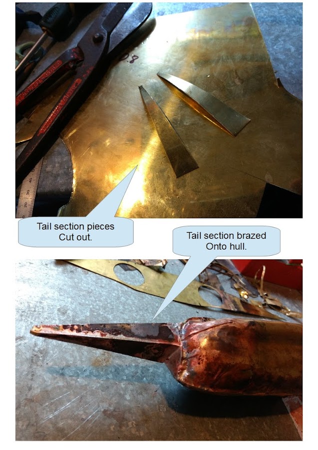
I started with the copper tubing, coiling it around a socket extension, & brazing a thin brass plate to the coil.

I also added a copper strap to the rear of the brass sheet, to provide support, & help with heat transfer. A couple of spare XM-L2 LED's were scrounged up, & re-flowed to a pair of 16mm copper boards, which I had previously hand-modded to make them DTP.

Before adding the LED's, the engine was tested in water with a small jet-lighter, & worked as expected. The LED boards were then soldered onto the 'engine', test leads attached, powered up, & tested again in water.

...Please forgive that mess....

Unfortunately, the copper engine seemed to be doing too good of a job of wicking the heat away, & I could not get localized boiling in the copper coil.

No problem - I'll knock up something else with more power...

Engine #2

This time, I thought I'd do a variation on the design, making a small boiling chamber out of brass ammunition shells.

Two shells were cut & brazed together, primer holes brazed over, & copper tubing brazed into holes drilled at either end.

I was hoping the brass would hold the heat, & with the addition of a little more power, courtesy of a pair of triple 219c's, we should be in business...

Engine #2 was rigged up on a 'test-raft', with a couple of ~half charged LG MH1's in Direct Drive. That should do the trick!

The engine gave a brief sign of life, prior to both triples letting out a whisp of smoke, de-soldering themselves, & plunging into the water....

I then tried using the mounting plate design from Engine #1, to give a little more surface area for the Noctigon's to hang on, but they complained again, & a wire de-soldered itself.

Time for another re-think....

Engine #3

After a long day with the first two engine failures, I figured I should sleep on it, & approach things fresh.

Water boils at 100DegC. Solder melts around 180DegC. Sounds like plenty of room to move, but the metal is working against me, drawing the heat away, & so is the water in the tube.

Getting enough heat through the brass to boil the water effectively, & maintaining that heat, was a finer balancing act than I had anticipated.

I needed to know what was going on, & I needed a finer control over the power/heat source.

The copper we all love was working against me, wicking away heat from the boiler. I had to make a new motor, entirely out of brass.

I started similar to Engine #2, but using a single, larger shell, & brazing in two thin brass pipes. The larger diameter shell allowed me to file a flat on it's side, to give the LED boards more surface area where they mount.

I went back to using the pair of 16mm boards with the XM-L2's, & used a Fet +1 driver with a good range of power levels to choose from at the top end.

The Engine assembly was mounted dry on the new "Dyno-Thermometer" rig for initial testing, where I could monitor the power level & heat.

When I was happy with the dry testing, & had the heat under control, I made a much sportier 'test raft', & tested again with water in the boiler. I settled on around 5 amps, which brought the water to the boil quick enough, but kept well short of the de-soldering red zone.

Ok - all aboard, & strap your selves in.....

www.youtube.com/embed/SOVVWLJlaIY

So, it's no powerhouse, but it will propel the vessel, & the LEDs are 'water cooled' to a certain extent!

======================

Body continued.

1st / 2nd October.

After going through the entire mould-making process again for the other side of the hull, I was finally able to stamp out the second side.

The sides are brazed together, & temporarily braced at the top for some rigidity, as the brass I ended up using for the hull is quite thin. ....(this will come back to bite me later on in the build).

There will be a light on both sides of the hull, & each will utilize an optic that will be affixed to a firewall panel.

I measured the spacing for the optics, then drilled out the holes with a step drill.

The firewall was brazed to the front of the hull, & Jack was left to clean it up whilst I started on the nose cone.

I wanted to try & keep the curved appearance going to the front of the ship, & decided to bend the nose cone panels between two pieces of piping, one of which had been cut in half down the center. This gave me a nice scallop in the panel, which matched the contour of the optic holes.

After a little more manual bending, both halves of the nose cone were brazed together, shaped a bit more, then brazed to the firewall.

After that, I cut out some pieces to make the tail section, brazed them together, & onto the rear of the hull.

The stepped area under the tail will house the rudders & Prop.

The heat from all of the brazing was starting to take a toll on the thin sheet that I user for the hull. I had thicker pieces stamped out, but opted to use the thinner material, as at the start of the build, I only had a butane torch which was not quite powerful enough to braze the thicker material.

For the nose & tail sections, I only have 0.8mm brass left, & had no option but to go out & buy a MAP torch. Unfortunately, the additional heat needed for the thicker sheet made it very difficult to braze to the thinner hull material, & it was overheated, which has made the whole job start to look a little on the ugly-side, & even burnt through in a couple of places.

Basically, the shiny brass boat that I had envisioned will probably end up looking like it has been on the bottom of the ocean since WW2...

I guess that would make it more authentic??

I could always give it a paint job to hide the sins, but that would add more time to the build.

====================

Fittings & Electrics

October 14/15th.

Whilst not ideal, things have improved somewhat in the cosmetics department. I can't undo the thin body stampings, & they have become a little worse for wear during the build process. But as far as shiny-ness goes, I think we are back on track, & it's all thanks to Jack & some acid. Take that as you will....

Before we get to that, there's been a lot of progress in the last few days, & things are finally starting to come together.

I decided that the access holes I cut in the main deck were not adequate to easily get all of the internals in place, so I cut out the center of the deck for full access. The new main deck assembly will be retained by a bolt that is brazed to the base of the hull, & passes up through the deck, so both halves will be clamped together. There will eventually be a thin rubber/foam gasket that seals the two halves when clamped down.

At this stage, I'm mainly making all of the small bits & pieces, & the off-cut/scrap pile is ripe for the pickings;

The prop was made from one of the original access holes that I cut from the deck, & the rudders from a cut & flattened bullet shell. The rear of the shell was used to cover the hole in the center of the prop.

The prop parts were balanced in place & brazed on, followed by the rudder plates.

I moved on to the new deck plate assembly, first using the cut-out scrap from the original deck to make the main turret front. The retaining bolt for the upper & lower halves of the vessel will pass through the turret.

The periscope will double as the fastener for the deck retaining bolt. A nut was brazed to the base of another shell, to thread the periscope onto the retaining bolt, & an off-cut of copper pipe was used as the scope lens.

Behind the main turret, there is a gun-deck. Again, off-cuts were utilized to make the deck & railing assembly.

Of course, a gun deck needs a gun! The end of a shell was used as the mounting 'pivot', & the gun is comprised of two short lengths of copper pipe taken from one of the failed engines, & a coupe of brass sheet scraps.

After all of the brazing was completed, the assembly was washed in water to remove any flux, then submerged into a bath of hydrochloric acid, which removes the black deposits on the parts.

Once removed from the acid & rinsed off with water, the assembly was rubbed down with steel wool, which removes most of the pinkish oxidization.

Here's the acid wash process being used on the hull assembly. The last picture is prior to being rubbed with steel wool.

Once the hull was cleaned, I lined the seams & joins with epoxy from the inside, to ensure there are no leaks.

Next up is the light engine & optic installation.

The engine pipes have to be inserted through the cut-outs in the hull first, & the engine slid back, prior to the optics being fixed in place.

With the optics in place, I used a small piece of pine to adjust the angle of the light engine, & slid the assembly forward to adjust the focus, so as the two beams merged. The pine block & engine assembly was then epoxied in place, & the exhaust pipes sealed to the hull.

I settled on using an "ML-102" charger to house the cell, as it sits neatly between the two exhaust pipes in the hull. I opened it up, & attached some 20AWG wires to the main terminals, for power to the driver, & cut & extended the indicator LED wires.

With this, I can run a USB lead to a hidden charging port in the turret, & also extend the charging indicator LED up to the deck, where I have drilled a hole for it, in front of where the switch will go.

Jack's made a start on polishing all the bits up, so hopefully next time everything will be nice & shiny

============================

21st October;

The remaining parts are pretty much done, & are in the process of being polished. Also, the electrics are all in place, aside from the Micro USB charging lead that I was hoping would have arrived by now. The USB lead will poke through the deck out of sight, between the gun turret & the main turret, where there is a small gap.

During the week, I snagged some rubberized foam off-cut from a local canvasser to make the seal for the access hole. It was glued on to the base of the deck & trimmed to size.

Today, I focused on making a display stand, where the 'boat will spend most of it's time "dry-docked". I used the last good section of the brass sheet, some copper pipe section that wasn't too mangled, & the other cut-out from the original access portal holes.

After the main bits were brazed together & cleaned up, I made a small plaque that was affixed to the base of the stand. I'll try to get a better photo of the plaque tomorrow, so you can see how bad Jack's engraving was...

Glamor-shots are not too far away, where we will finally see the 'boat fully assembled & lit-up, on the stand.

Of course, we will also find out if the vessel is "sea-worthy", when Jack attempts a full-power run, for it's self-propulsion party-trick!

============================

22nd October ;

The build saw it's first complete assembly today, aside from the missing micro USB cable. Here's a picture of the charger in action, & also where the micro USB connector will go, in place of the temporary full size connector. The micro connector will sit down lower, out of sight. If the new cable arrives during the week, I'll update with another picture.

======================

Update;

The micro USB cable arrived yesterday, so the build is now completed.

My dollar store "5 minute" epoxy that takes overnight to cure was used to secure the cable in place, hidden inside the turret. The cable is about 15cm (6") long, so it loops nicely inside the hull, plugged into the charger, & has plenty of length to remove the top section.

As a bonus, the light will still operate on lower modes without the battery inserted, when plugged into USB power. With this, the light could be left on indefinitely in a low mode, on a shelf, or display cabinet.

========================

Now, everything is looking shiny & ship-shape, thanks to Jack.

It wasn't without drama, though. I knew something was up, & it turns out that one of Jack's "kamerads" from back at the docks got wind of the project, & had been hounding him to partake in transporting illegal substances in the hull of the 'boat. Jack refused, but he knew it wouldn't be the last he heard about it.

Early this morning, "kamerad Johann" entered the shed whilst Jack was putting the finishing touches on the 'boat.

The following scenes are Jack's version of the event;

This obviously set things back a little, but after the "trash was emptied", we were able to test the assembled 'boat in a confined aqua-facility.

===========================

Later in the day, we transported the 'boat to the test-tub, where Jack made some preparations, & finally it was launched.

After adjusting the center of gravity a little via some lead inside the hull, the 'boat sat at a nice level, with the lights submerged & working nicely.

If the seal & switch assy. was 100% waterproof, I would have been able to weight the 'boat so it was even more submerged, but this will have to do.

After a short warm-up period for the engine, we have some propulsion from the exhaust :D

As you can see, the boat is all nice & shiny now. I took a few snaps of the finished product prior to the water test, just in case everything went pear-shaped!

There's a bunch more photos to go through -I'll sift through them & post more up in the OP later.

Thanks for looking :)

========================

---------------

------

--

Wolfenstein, hehe. :smiley:

first flashlight to fry eggs and blind your enemy permanently?

:smiley: :+1:

HaHa! LOVE the Teaser video! :partying_face: :+1:

Remember “Is Don, is deadly” :disappointed:

Cheers David

Fortunately, I wasn’t into smallgoods at that point in time!

Can it shoot down a North Korean Missile?

Mutti…

Nice start. :slight_smile:

Who says I’ve actually started!!??

Long weekend here, & I’ve barely done anything aside from loose sleep…. :person_facepalming:

The video I was referring to. Its more than I have at the moment. :slight_smile:
You can catch up on the sleep when you go back to work.

Build revealed in OP, & a few updates in post#2.

Wow Jack is super clever at helping. I wash the sacked assistants were just as helpful.
Your build has a lot of intrigue factor built straight into it. :slight_smile:

A little more work, post #3.

:+1: :+1: Delving into new fields…. :smiley:

Thats going to be one big boat as I see your using a 45Kg gas bottle for the mold. Did you get a discount on a truck load of clay?

I may be crazy, but as you will not need it to deal with implosion pressures would it be easier to build it out of fiberglass or even carbon fiber?

it would be cool to have the (im assuming search lights) be water cooled.

heck get fancy and use the led(s) to make steam which drives the prop?

yes I know, crazy