I haven’t looked in depth, but I thought EL wire required like 100-volt alternating current at about 1000 Hz? It would need an inverter and a serious voltage boost and the frequency would likely be audible… I don’t think it works at higher voltage or inaudible frequencies, does it?
I thought it sounded like a fun addition to some projects… until I found out it required alternating current.
The only thing I can think of for some semblance of practicality is a wider body that can house two separate circuits. Kind of like a Spy 007. We could use 2x CR2’s to power the inverter, and maybe a 16650 powering the LED side.
No, it wouldn’t be ideal, but it sure would be attention-getting!
The last one I did had 6 slow colour-changing leds and was lots of fun. The only unexpected effect was that with the 6-led dumb board, every 2 leds share a resistor and are directly parallel, and when at one side the low voltage red led was lighted, a higher voltage blue one parallel would not light up. This led interaction was very interesting to observe but you hardly saw a blue one lighted at all.
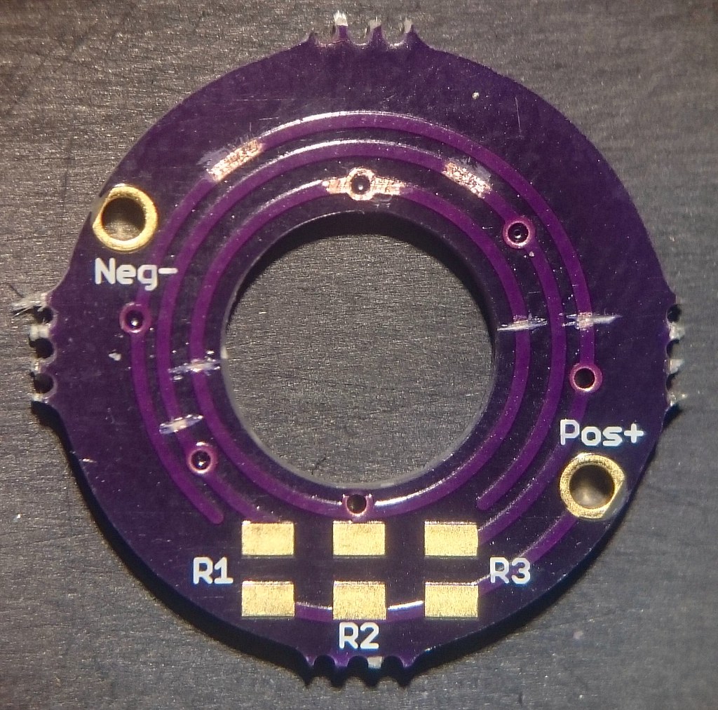
Yesterday I did a new Jaxman E2L mod (see the wdymt thread), and today I thought it was neat to have another disco-tail made for it, but now with each led behind its own resistor. It required modding the tail ring. First some traces were cut and solder pads created:
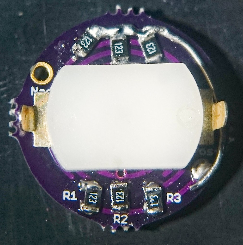
Then the six resistors were soldered, clearing the area where the switch touches the board. The 3 extra resistors were connected to the plus-pad with a thin copper wire:
Then the 6 RGB leds were soldered.
Every tiny component and pad was tinned before soldering down, as I learned the hard way. * Steady hands and perseverence alert! *
The result is as predicted: now all six leds work independently. But they have no synchronised cycle so after switching off the light each time they start together but soon they run out of phase :partying_face: :
This is great! I’ve only built one of these tails and I liked it well enough, but mine, just like yours, would “drop” blue within a few cycles. After 30 seconds or so they basically became reds and greens only, mostly reds. I had no idea what caused it but never built another because of it. But now I do! Thank you!
I have Astrolux tailcap switch from BG, the switch comes with only 1 led and 1 resistor (blue 1206 led and 2K 0805 resistor).
Already installed (the same 1206 blue led and 2K resistor) another led and resistor on the other side so I can have balance light from the switch. The problem is, after installation, the original led is very dim, and the new led is bright. Check all solder and nothing wrong. Anyone can help? This is the switch board. Thanks.
Actually, I already tested that. Solder the led first with no resistor (only 1 resistor with 2 leds), the result is new led bright and original led very dim. After that I install the resistor, so 2 led and 2 resistor, but nothing change. Same result here.
If one of the leds is original and the other is from a different manufacturer, then that could be it. I would try matching the leds since they might have different internal resistance.
Would like to share few lights nothing fancy. currently not using any ring pcb/boards, using white 3D printed rings instead of the metal in convoy not so bright compared to rev2 board because of the ring blocking the light looking forward when rev2 boards arrived from OSH.
I have S2+ with metal tailcap, but i’ll wait for rev2 boards as without it the light is just too dim with low current.
Just saw this djozz. That’s spectacular. Have you done power draw tests on those color changing LEDs? It’s this kind of stuff that makes me want to come out of modding retirement :heart_eyes:
Thanks pd, and now someone will have come up with yet another cool mod to definately get you back on the modding track. :partying_face:
The tail draws between 0.4 and 0.6 mA, so the Aspire 18350 cell that I use in the light drains in about 100 days.
I have EDC-ed it for two weeks now (a E2L triple with 219B SW40 R9080 makes a great EDC) and the only time the slow-disco-tail was a bit hindering was when camping on a camp site I had to find my way to the toilet in the middle of the night, I was glad no one saw me grabbing a colourful lighted thing out of my pocket and wonder what on earth that was. Once clicked on moon that solved the situation of course.
Rev4 19mm board for my shorty L2M finally arrived. Less then 3 weeks to Indonesia is fast enough. When inspecting the board, I realized that the led position is near the edge of the board which mean led almost underneath the tailcap body. So I think it will need led with larger emitting area to spread the light more, using 1206 smd led instead of 0805. The led pad is designed for 0805, have to solder at the edge of the pad to fit 1206.
Using 1206 smd in red and 2K resistor.
Bright enough and apparently the light is spread nicely. The interior of Solarforce tailcap is bare alumunium (not anodized), kind of reflective. So with the combination of bigger led and reflective tailcap interior, this is the result.