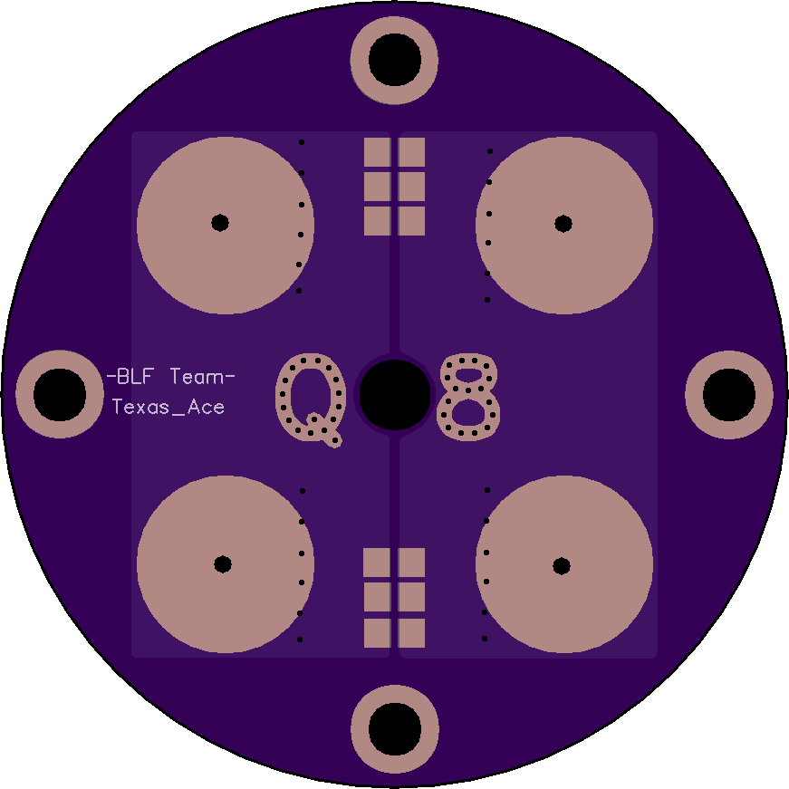
I have been thinking about this and there are a few issues. The first and largest issue is that we have no control over how the cells will line up with the driver, making this much much harder to do if the driver is screwed down. Almost impossible if screwed down.
The drivers will most likely need to be press fit / glued in place in order to line up with the cells properly.
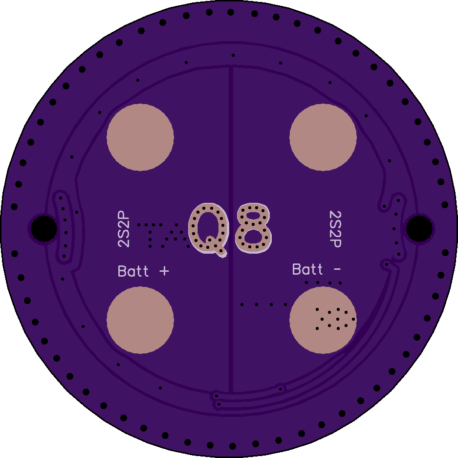
The V+ and ground pads need to be isolated and the other 2 pads electrically neutral but connected.
As it is the V+ and ground will short out to the other 2 cells, which would get real interesting. Kinda curious if the copper trace would melt in that situation.
The spring pads also look pretty small and pretty far out, are you sure they will line up with the cells? Seems like they should be a lot closer to the center then that.
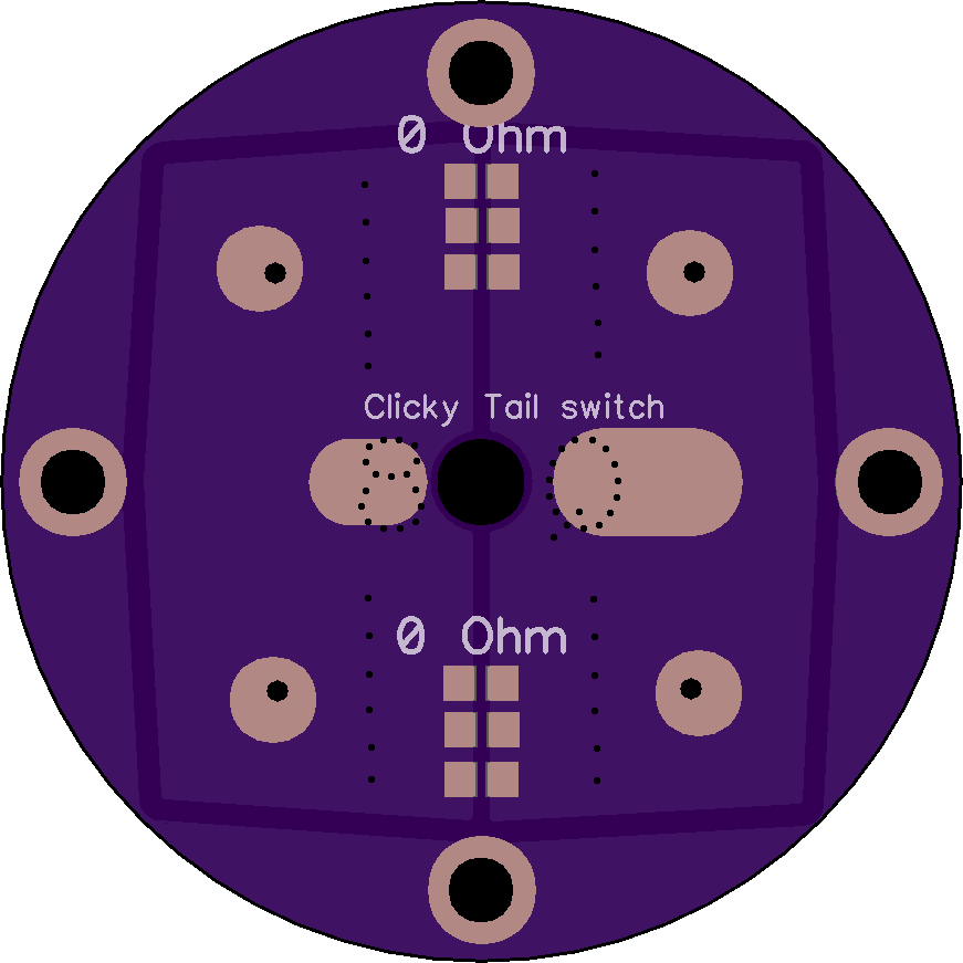
Interestingly I discovered by mistake that 0 ohm 1206 resistors actually work as fuses if you short out the cells. Long story short, I used then in the tailcap of my mega M6 build and when I was putting it together and mistakenly mis-alinged the tailcap while trying to get an amp reading.
Well there was a spark and then the light would not work anymore. After troubleshooting for way longer then I want to admit I found that both of the 0 ohm resistors had blown and acted like fuses. Interesting thing to keep in mind.
I missed the 2s2p, I was thinking 4s1p as it would be better for every situation I can think of. For 2s2p this would be correct.
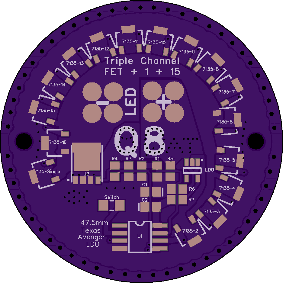
Although honestly I have had very bad results trying to use the 7135’s with a high output 2S light, it tends to be luck of the draw weather they live or not. I ended up giving up on them and just using a plain FET only setup for 2s and 4s lights I would not want to even try to find the bad 7135 with 16 of them to go through.
There was a 12V capable 7135 replacement posted recently that could work for this.
For 2S lights the A705NGT might be of interest. They are basically 7135s that are rated for 12V. I’ve just built a 6V MT-G2 headlamp based on them so I’ll be giving them a go.
For the Q8 I have a 4S design on the way for XHP35 HI with ATtiny1634 MCU and CAT4101 regulators (controlled by digipots). The CAT4101 may well be a bad choice at a high price tag, but they are easy to use for an electronics noob like me.
Well, I got one design, but I found a different buck controller (that should be better than my first one) yesterday. I probably make a second board with the new IC.
The Texas Buck should work as a base for a Q8 buck driver, although it would not put out as much total power as the Q8 does now. Although I think we have found some better PFET’s to use compared to the one in the design.
The only practical way to make a buck driver work in the Q8 is to rewire the cells to be in 4S. There is simply not enough voltage overhead and you need too much current to make a 1S buck drive practical.
I used the ISL8117 in a 4S configuration and it should be able to output 20A.
Edit: But with that controller you need an inductor with 10uH (limiting the current capability), but now I found a controller that needs 4.7uH (with the same frequency and more efficiency, and the frequency is pretty low for less switching losses).
Hmm, a quick glance at the ISL8117 looks really interesting. I really like what I saw, that indeed would seem to make a good IC for the Q8, it is even small enough that it could fit on some smaller drivers.
Whats the new IC you found?
I am actually working on another project where we are trying to drive 15A+ on a buck so a new option would be nice.
The other one I found is an LM5145/LM25145. They both are nearly the same controller, the LM5145 has a higher maximum input voltage: 75V compared to 42V at the LM25145. Everything else is the same.
I stand corrected, I found it now… Pretty odd, shouldn’t matter what EU country they send to.
Well, I’ve been using them in one of my headlamp projects and they work alright, but the ones I have don’t draw 330mA, the consistently draw 250mA. I had to check if I got the wrong ones, but they are marked as 330mA versions. Other than that they same to be very reliable. I’ll be trying to get the 350mA versions next time.
So if I understand correctly one could make a driver working on 6V input and with the number of these chips control the output?
Like a 8*7135 for XPLhi, we could make a n*chip for XHP70.2?