What did you mod today?

I’ve completed the stand, it’s in place and waiting for the power supply.

I was hoping that the high CRI combined with more lumens would make a large difference. The MT-G2 is currently being run by a 6V 1.5A wall wart, so it’s pretty underpowered. The Reaper is growing under it though, hence the thought that better light would let it grow faster. :slight_smile:

I went ahead and modded first custom firmware, for the Emisar D4.

Very simple stuff (not like I have the knowledge to do anything fancy). I just removed the mode memory, (Or rather, it always remembers the same level) and now, a single click will always take me to full 7135 power (125 lumens). This way, I always have access to moonlight (long press) medium (single click) and turbo (double click). And if I need any other mode, the ramping is still there, right after moonlight. Basically, I don’t like not being sure about what my flashlight will do once I press a button, so I dislike memory mode. So now, I have the best of ramping UI (being able to choose any specific brightness I want) and the advantages of discrete modes (easy to get to certain pre-defined levels).

Took a few tries, but luckily, my driver testing setup worked well enough.

I also changed the led leads from 22awg to 18awg. It had no effect on the output, according to my “approximating sphere”.

Now, I’m trying to find a way to remove the tailcap pcb, so I can place a magnet there. With some luck, a 1mm or 1.5mm magnet will have enough strength to hold the D4 up, which is the biggest magnet I figure will actually fit in there.

Nice adaptation kaybi, that would improve the D4 for me too, my fixed brain can’t handle the uncertainty of MM. Unfortunately I don’t have your computer skills.

About the tail PCB: be sure to want to remove it, it ensures the manual lockout even once the anodisation in the threads has worn away.

Oh, no, I would remove the tail pcb to add the magnet between the tailcap and the pcb. So it would be put back in place afterwards. Which is why it would have to be 1 or 1.5mm, since it can handle cells up to 67mm, according to TK.

If you can’t flash the driver yourself, I’m sure someone else on the forum would be willing to. I would do it, but I live in Spain, so shipping the driver back and forth would cost as much as a new D4.

The modification to the firmware is easy as it can be, but I would be happy to provide the .hex if needed.

Nice! I knew you’d like firmware mods Kaybi.

Yesterday I did a very experimental mod, I modded a Securitying AA zoomie (I bought it here) with a bistro driver and an Oslon Black Flat. The experiment was that the Black Flat was reflowed on a DTP-board, but to prevent electrical contact between board and pill (the thermal pad of the Black Flat is connected to led-minus), it was glued in with Arctic Alumina Adhesive. The question was if the thermal transfer to the pill would be high enough for this high power mod.

The answer is: no. The drive current on a purple Efest 14500 is over 3.5 A, with the output (flood setting) within 30 seconds dropping from 500 lumen to 275, so 45%. This is even worse than the first DQG tiny 18650 with its XM-L led on a frp board.

Still, the Black Flat is a tough led, so despite the huge temperature sag of the led, it works fine, and it has become a pretty impressive little flashlight. The numbers (37kcd at start, 27 kcd at 30 seconds) are worse than my best dedomed XP-G2 AA zoomie mods with same 18mm lens size (42 kcd steady), but the spot that the Black Flat produces is far better looking: very distinct square with even illumation, no dots.

Here’s a few pictures of the mod:

The lens was taken out and replaced by the lens from a sk68 clone (sanded the side to fit), this lens has a shorter focal length and enables focussing the spot to a sharp image of the die (the stock lens did not do that)

The stock driver is 14mm and clamped in in a weird way. I found that an exactly 15mm driver could be clamped in between pill and a tiny edge on the inside of the battery tube, it just needed sanding 1.2mm off the underside of the pill. I used a 15mm Oshpark board (made by Warhawk at the time) filled with the components taken off a Banggood X5/X6 bistro driver, except the FET that is too big, I used a LFPAK33 FET bought from Mtn Electronics.

The glueing in of the ledboard was a stressful and dirty job it was difficult to keep the board insulated, and when the adhesive was almost completely set I discovered that the holes did not line up and the board needed twisting, I barely managed to get that right. I made a 10 minute video of the process.

The led under lens in the finished light

Beam on the wall

Beam on the roof at the other side of the square, roof is at 40 meter.

That little corner on the LED pattern is a shame. Too bad it isn’t a full square.

There is a newest version of the Black Flat, with even better thermal resistance and without that corner, unfortunately only the 3-die and 5-die version is brought to the market, the single-die one is not being made (yet?).

Not yet. We should be ready that most modern small die leds that are made for automotive industry couldnt be used in flashlights.
But, anyway this osram leds looks very pretty in comparation with crees. Lumens drop from temperature increase is much smaller, this can make big sense in flashlights.

MT-G2’s make great little grow lights. Here my crystal red shrimp tank. Its only source of light is the mt-g2 I have wired up to a wall wart. All the plants in the tank are very happy.

I am curious how well the upgrade cobb led works out though.

Upgraded my plant light by removing the Delrin plug and making an aluminum tube for it so heat would rise through the aluminum and also up and out… even the rod it hangs on will help disperse heat. So now I’ve cranked it up to a steady 0.425mA and it’s making 962.55 lumens via my light box…… I used the meter to measure at the ground level outside and this light is making pretty close to TX sunlight, without the massive heat.

With holes in the aluminum tube spaced at 1/2”, and holes in the vertical post at 3”, I’ll have nice adjustability as the plant grows.

electric jelly, your shrimp look content under that MT-G2, what power level is the wall wart or have you measured at the emitter? I went with this COB as I knew it was rated at 90+ CRI, and it makes a nice floody light with no artifacts. (and I had one sitting around doing nothing)

Edit: Since I changed from the MT-G2 to the CXA1512F COB (Aug 19, 2017) it’s been really growing, you can see daily changes easily. Like a hot little weed, it is! :smiley: (Yes, the past 3 days have shown a marked growth improvement. :smiley: )

Now, I’m trying to find a way to remove the tailcap pcb, so I can place a magnet there. With some luck, a 1mm or 1.5mm magnet will have enough strength to hold the D4 up, which is the biggest magnet I figure will actually fit in there.
[/quote]

Your answer is here

Cheers

Kel

I have tried to asked this question several members in pm, but had no answer. Seems this is proper discussion in this thread now.
How can we compare “white” leds with wide spectral range to special leds made for plants growing? Is it possible to calculate independent lumens for specipic nm range, and compare this numbers with lumens measured from special leds? Last number is also problem cause manufactures usually give numbers in some specific value that cant be easily taken with general meters.
P.S. In my suppose, new white leds have so big full output that probably (mostly high cri leds) have enough output in specific nm range to beat special leds with their tiny output…

Reaper grow time-lapse!

There is ongoing development in what spectrum is considered optimal for plant growth. And that spectrum has moved a bit more towards a full sun spectrum. So the bit weird blue/red mix of leds as plant growth lamps currently may not be best anymore.
I found this (not too smart) article (by a company so it may always be biased): https://www.redusystems.com/en/innovation/entire-par-light-range-has-function-for-crop-en/and

I know that some companies use white leds, others mix of color leds, and all have achievements.
Im interested in ways of measuring, calculating and comparation leds with wide and narrow spectrum range. How to get this umol/s and umol/J values? How to isolate narrow strip from full spectrum wide led diagram and get right values? (I suppose that some special glass/plastic pieces that can pass through narrow range are needed.)

Finally started on modding my Haikelite MT03 I bought back in May. After tearing it down, discovered couple issues.

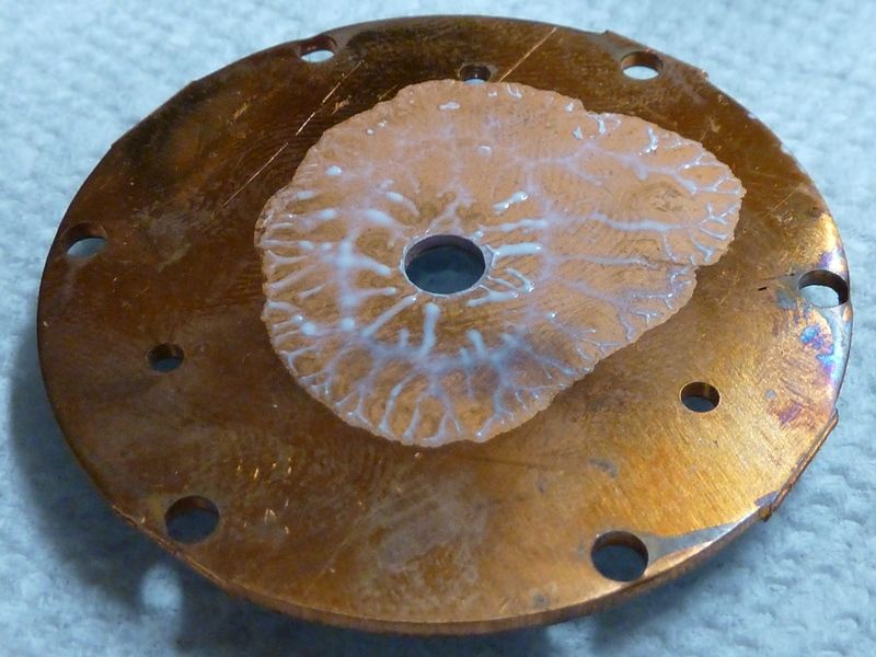
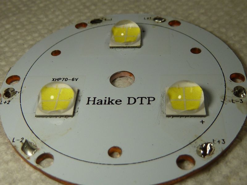
One dab of grease, only covers about 50% underneath the 3 LED's, plus jagged wire holes:

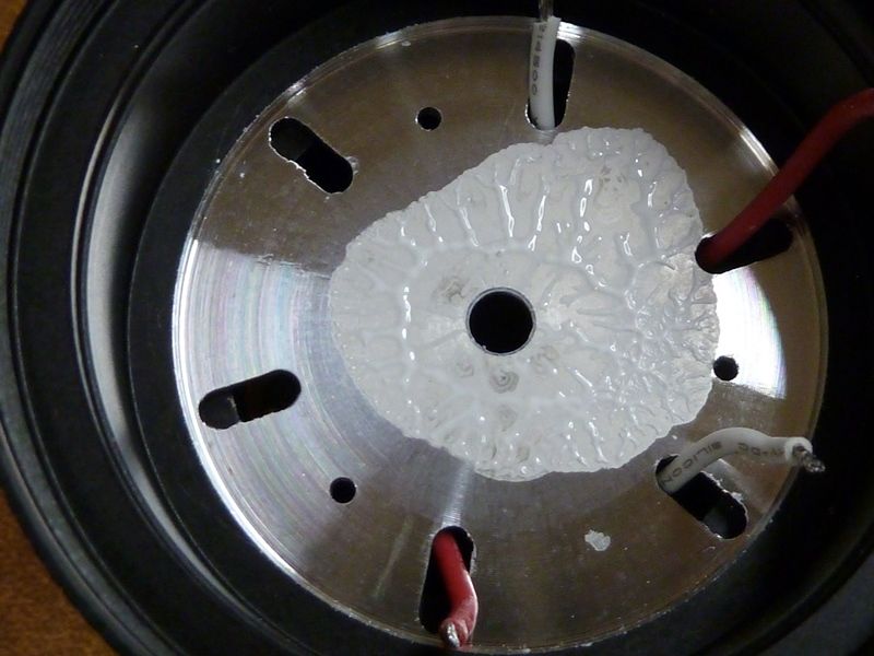
Tarnished up copper:

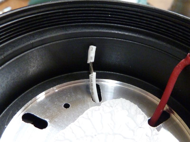
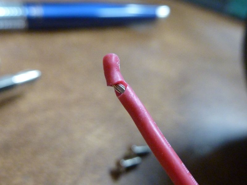
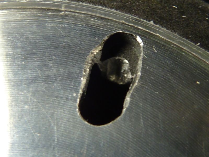
Not only jagged edges, but the wires were pinched on an edge of the housing, so they tore when removing them (I hope it was upon removal...):

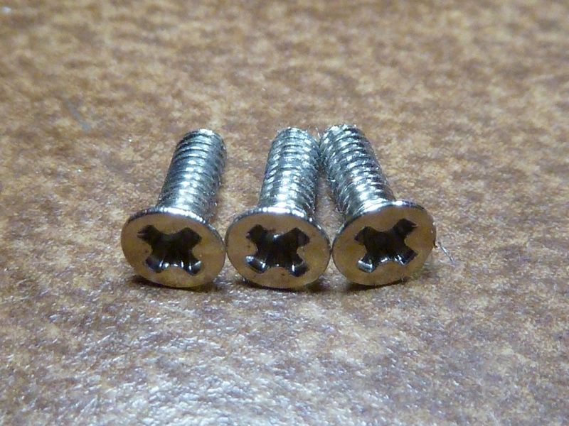
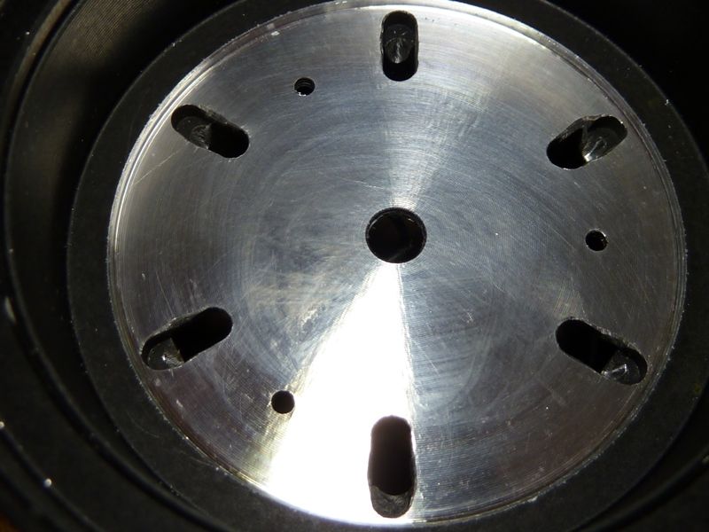
These are the screws holding down the MCPCB. They look ok, but they don't tighten - threads in the shelf are stripped:

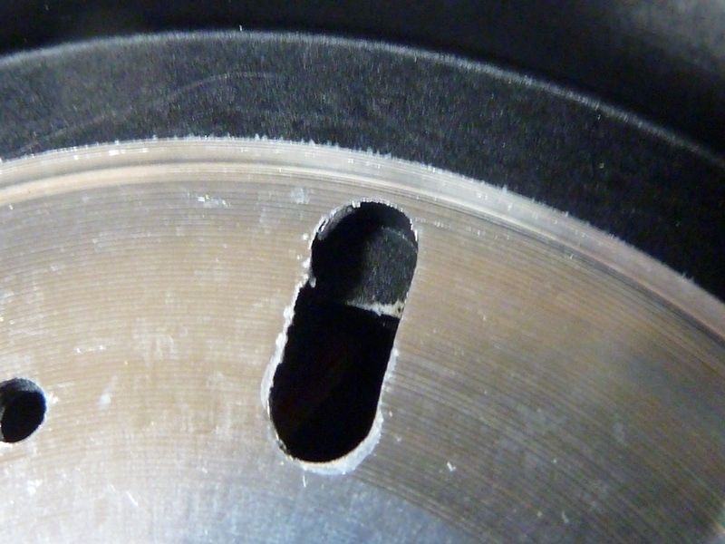
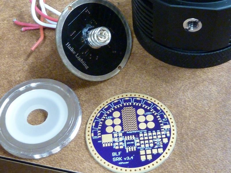
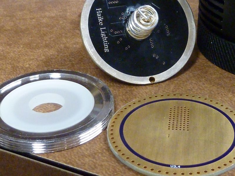
Here's the wire shredder and pincher:

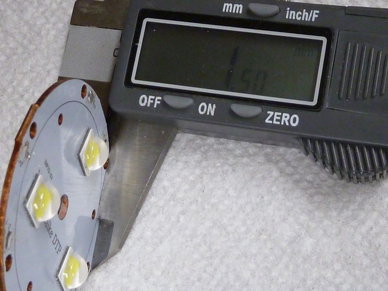
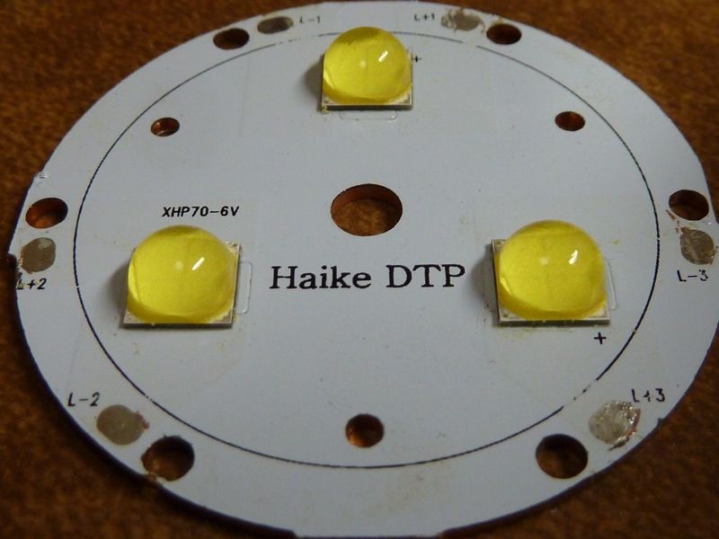
MCPCB feels pretty thin at 1.5 mm

for such a large one:

Lot a little solder balls:

This is after some work - used the rotary tool to drill out thise pinching edges, and angle cut those sharp edges off on the holes:

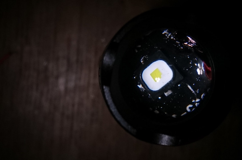
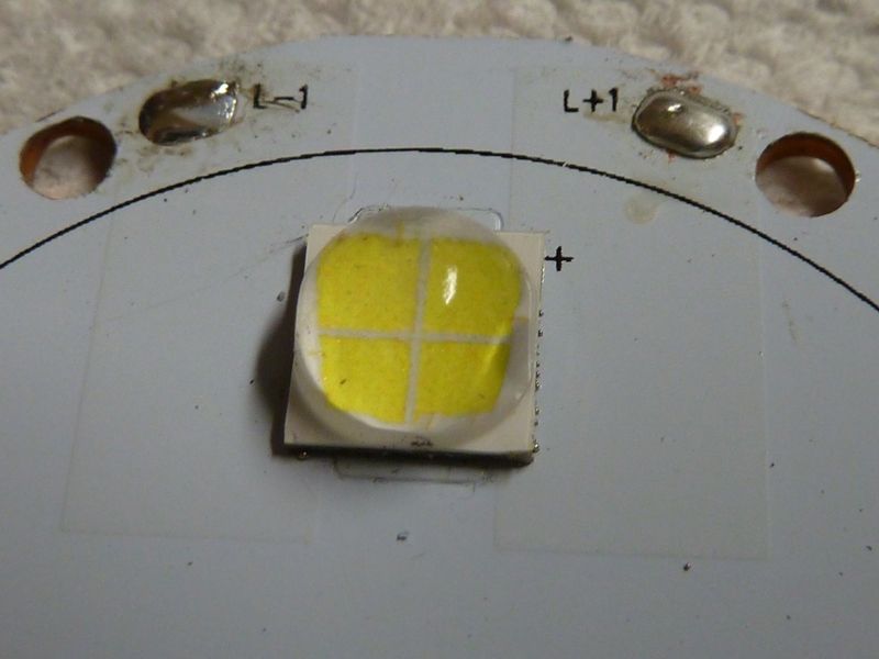
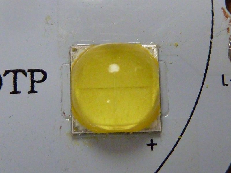
Reflowed the XHP70.2 P2 3B's,trimming off the yelloe covering on the corners. Dunno if will help, but I know KawiBoy said it improves the beam on dedomed LED's. Hoping maybe it will reduce the yellow halo, maybe?

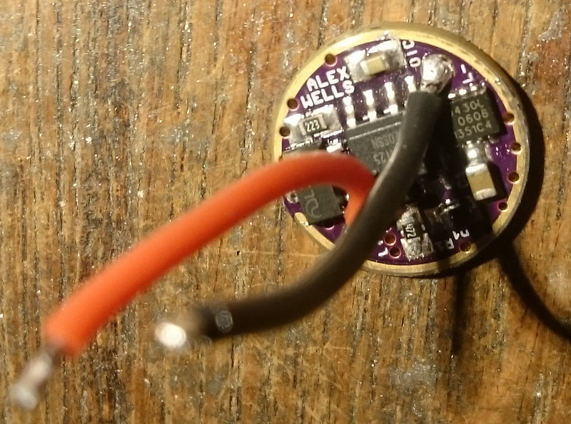
The latest SRK LDO driver from HQ seems perfect for this mod. All I had to do was sand off the tabs on the edges, and it fits perfect under the heavy retaining ring. I'll just transfer the double springs over after reflowing the driver. I test fit the driver, did continuity tests and the grnd ring contacts perfectly.

With a 2S2P battery tube, it's a fairly easy mod, and love the bulkiness of the MT03 - still compact but more heat sinking I'm hoping, because the amps will sure get up there. I'll probably use a SIR404DP FET and a single 7135. The HQ driver is very flexible and versatile for configuring it in various ways.

If you use a wavien collar then it becomes nearly invisible thanks to the reflected die image and white material around the die.

Interesting…

All early Vinhnguyen(famous CPF moder) mods were don with AA adhesive. But they were applied very thinly and under hard press on classic cree leds(xpg2, xml2).

The problem with osram leds is that you probably can’t give them hard enough pressure that will squeeze excess off AA and stick it firmly to pill for better heat transfer cause it will start making contact with pill anyway and puuf! I tried that kind of pressure on 4715as and poof happened… Method I use now for Osram IR are gentle circular moves, and only pressure is pressure from tweezers so I actually feel when AA starts spreading under dtp board. I don’t see or measure any performance drop on that kind of builds but they are only up to 2A.

@l.i.
Yes, the AA layer was much thicker than it would have been if I could just press it down firmly, it shorted if I did that. Perhaps someone will manage to get the layer thinner still without shorting it, but in my case with resulting heat sag the Flat Black looses the competition with the dedomed XP-G2. I doubt even if the heat sag is better than if I used a non-DTP board.

The trick will probably work much better in a mod with one of those chunky Maxtoch boards: more surface area to transfer the heat, and if the host allows lapping the upside of the pill so that both surface are nicw and flat, you can make a nice thin layer of AAA.