Sure, it would be possible to record, for example, that the light was turned on 1, 2 or 5 seconds the last time. But if we started making distinctions, we'd end up with something like "turn light off within a short period of time to do A, and to do B, turn it off within another, but different, period of time". That would be very confusing.
The problem is that the same action is used for different things. Turning on for a short time (let's call this a 'tap' for now) means either changing modes or, if done repeatedly, going into programming mode. Maybe a single tap shouldn't immediately start changing modes, but instead be used for shifting functions? Let's say, a single tap does nothing. Two taps get you into mode shift, where you can cycle through the programmed modes, four taps let you cycle through all available modes and six taps get you into mode programming. The main problem with this approach is that people unfamiliar with this UI will be very confused.
ISP programming uses four control/data leads plus power and ground. If you're willing to temporarily dedicate a driver PCB to development (and have a steady hand), you could just solder leads to the pins and terminate them in ATMEL's standard 2x5 ISP plug. This way you could simply plug it into the USBasp. Or if you just want to play around with the program logic, you could use something like this: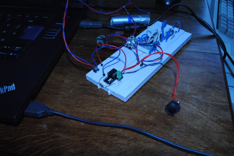
(ignore the upper half of the board, that's a loftover from a different project). I'm using a normal DIP ATtiny13 for developing the program logic and only use the driver PCB for testing with real light levels. Keeps the risk of being blinded by accidental mode changes to a minimum 
