what are your goals on input and output current/voltage ripple?
The overall setup is 6S6P input with an 18V LED output with a total current draw of ~30A.
Ripple should be as low as is practical, we are working on the rest of the setup and going to kind of see where the ripple ends up. Looking like it should be around .25A or less from early calculations IIRC. The real issue has been finding a PFET that will work.
The project has been on hold for a little while now while the manufacture tries to find a PFET that they can source that would work.
6S6P? Probably need a backpack for that ![]()
Lets just say that this is not a light that will be an EDC choice lol.
Seeing how TomE gets 27 klm with triple XHP70.2 in MT03 I really wish to do a similar thing with Q8.
Having quad LEDs it should certainly do 30k. It would be even better when running 12v. But there’s no XHP70.2 PCB and no suitable FET+linear drivers……
I don’t think you realize how hot the Q8 would get at 30k lumens. Going off of past numbers for the XHP70.2 at those kinds of outputs.
You are looking at around 120 watts per LED.
So around 480W total output.
To put things into perspective my SRK mods that are doing a mere ~150-200W get hot in about 30-45 seconds (think BLF A6). With 2-3x the heat you are literally talking about 10-20 seconds to get hot.
In addition to this, most cells can not support that much output.
Most cells are only rated for a max of 20A with a few reaching 25A. You would need cells able to support ~35A each to power this safely.
So while yes, it could technically be done. Is it really worth it? That is up to each persons wallet I suppose.
I can say I rarely use my 8x xhp50 SRK as it simply gets hot too fast to be useful, even if it makes 17k lumens. I prefer my 10-13k lumen SRK’s that are much more reasonable.
I have never used anything like that, so maybe I don’t realize. But it sounds like my D4’s bigger brother. I have the hottest variant, use it with VTC6 and ordered VTC5A because I can’t have enough.
My novice thoughts are that using 4x XHP50s is about as much light as you can get out of the Q8 practically. I got my first XHP50.2 light and it does about 2000~ lumens from 6-8amps and isn’t busting a sweat in terms of heat during extended running. In the long-term I do not see my Q8 being stock forever(not that anything is wrong with it), but I am on a unending quest for more lumens. Though 20A per cell in a 4x 18650 light doesn’t sound unappealing… I’m not ready to put that many watts in my hand just yet.
> that many watts in my hand
Yeah, the main mod I’d like to figure out is a way of handling the heat.
Not that I want the flashlight to end up looking like the International Space Station, which has its huge heat radiator panels (almost as big as its solar photovoltaic panels, but aimed differently)
But there’s stuff, like: Heat Pipes | Advanced Thermal Solutions
Pre-made, many sizes and shapes, copper with distilled water inside, ready to be soldered to a heat source at one end and a heat sink at the other….
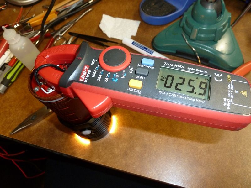
Just got in some new batteries, thought I'd test them in the modded Q8 from round 3, and show some base Q8 stock measurements vs some relatively simple mods as noted:
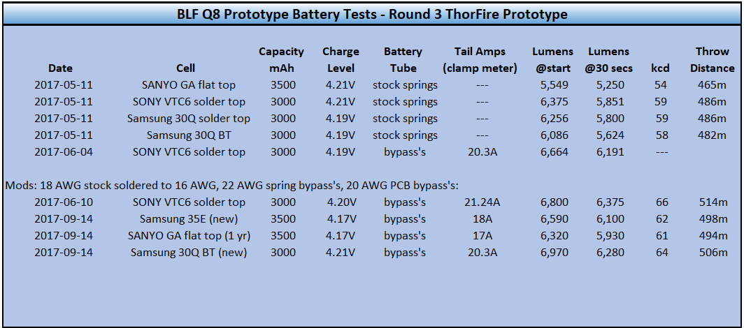
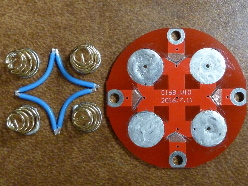
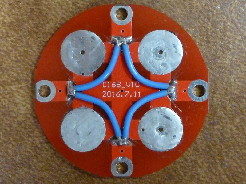
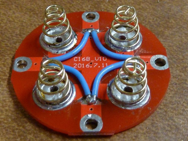
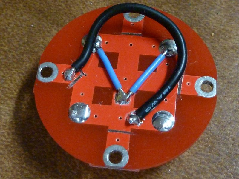
The tail PCB was modded to build in a high amp loop for measuring with a clamp meter, plus bypasses added. The blue wires are teflon coated, i think 20 AWG:
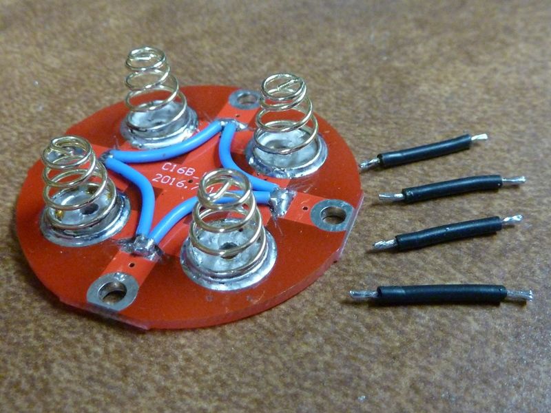
![]()
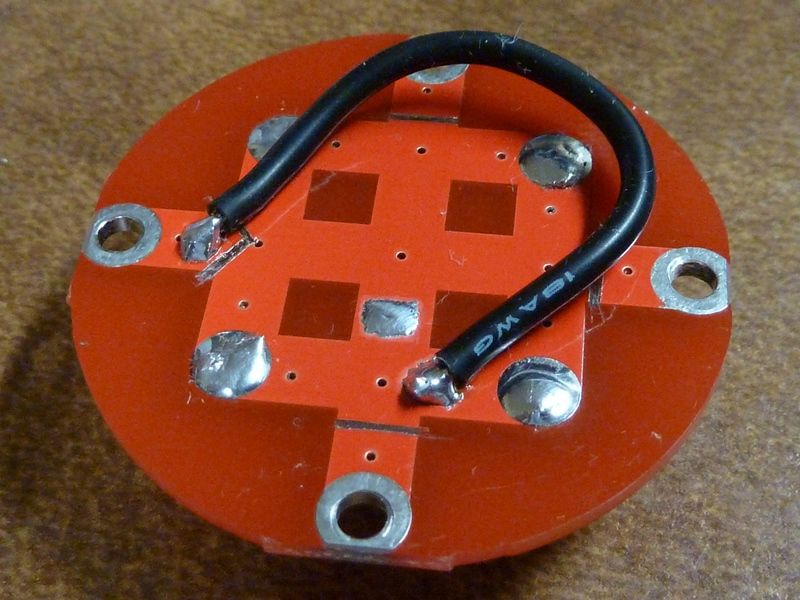
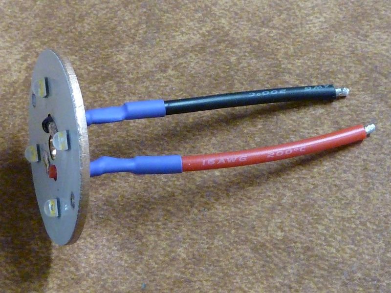
This is the stock 18 AWG wires cut back, the soldered up to 16 AWG for the longer run to reduce resistance:
With 4 XPL2's in an early Q8 prototype, I measured 26A using the same wire loop setup, and output was higher even with V5 bin XPL2's.
and did you burn a scorch mark on that desk?
Mica can take it - I do my soldering on that surface - not a mark. It's actually an old secretaries desk I bought at a going-out-of-biz auction back in the 80's.
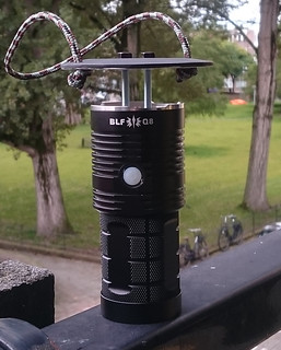
I made a lantern attachment for my Q8, see here in the WDYMD thread: What did you mod today? - #3529 by djozz
![]()

Looks like maybe a quad of triple or quad tir optics. Really nice heatsink mount there. In theory I suppose you could get 12K out of it, maybe better. Other option for high output is 4X XHP50's, but that requires the 2S conversion of course, but TA and Lexel have the OSHPark boards for it already.
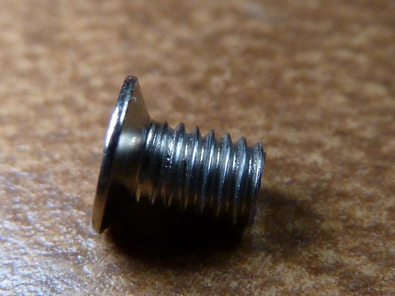
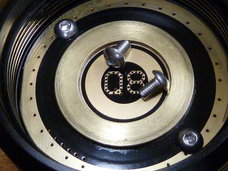
Stock driver retaining screw, pulled. Threads look good to me:
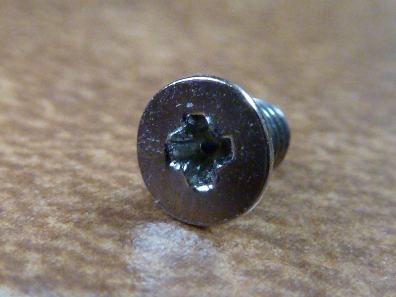
Bit of stripping in the head:
I used these as a replacement. They seem about dead even with the brass ring. I drilled out the holes in the driver a little bit so the screws do not have to be threaded through the PCB - they clear easy now:
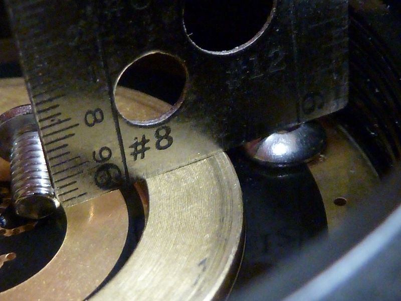
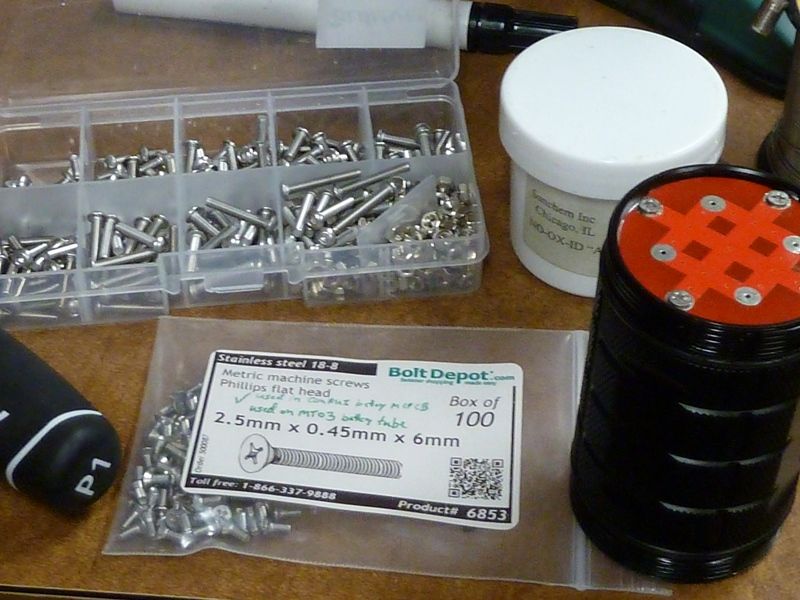
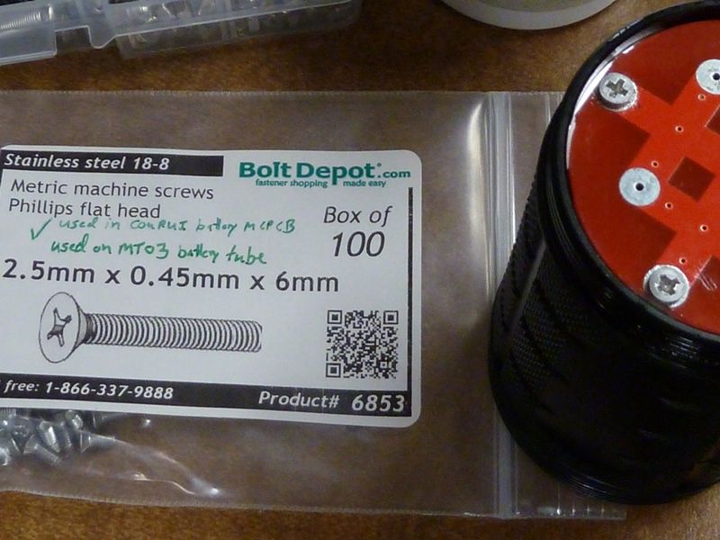
The tray on top of the pic is an assortment from BangGood here. The M3x5 is what I used. The 2.5mm x6 mm are the ones I used to replace the tail PCB flatheads:
I'd rather use panheads on the tail PCB - have some on order.
nice Tom
Like the look of the driver without plastic a lot
And by how far do the screws clear the batteries? There are flat tops that protrute a bit so can be used in the Q8, also they should be cleared I think, not just the button tops.
Sure the flat tops will have more clearance, but pan heads or round heads induce no stress on the board, better electrical contact. Also you will see when you get one, those flatheads require the tolerances on the holes to be perfect, otherwise the screws won't set down well. ThorFire did the right thing in having no anodizing on the surface in the tube for the tail PCB contact, but the PCB board contact pads seem lower than the surrounding solder mask, so not sure those pads are even making contact. Soldering them would help but may be hard to get a consistent thickness.
It's hard to tell for sure what's going on but I was getting lower input on Q8 2 of 3, so I used #2's battery tube on #1's head, I could reproduce the low output. With the new 2.5x6 screws and NO-OX-ID treatment on the screw, it appears like I got rid of all the loss's. can I be certain of that? No way - too many dynamics, variables, uncertainties. I'm still not sure, but tightening the tube harder gets better output sometimes. The tube edge to driver grnd ring contact are barely touching on the outer edge of the grnd ring.
It would definately help to cut the threads again in the tail to remove anodisation
+1 for flat screws, but I would file the top of em rather than drilling in the board