The Q8 arrived a few hours ago :partying_face: .
The Spring PCB is already modded ![]() . Pictures will follow when my cam is charged. Now i have to go modding the other end. New switch LED´s and a new resistor (the LED´s are way to bright for my taste) and then change the XP-L wires with 16AWG.
. Pictures will follow when my cam is charged. Now i have to go modding the other end. New switch LED´s and a new resistor (the LED´s are way to bright for my taste) and then change the XP-L wires with 16AWG.
Only with spring bypass and thicken the traces i got 20,8A out of my VTC6 @4,05V. With one VTC6 i got 15,8A. With two i got the full 20A.
I am curious what i will get after changing the XP-L LED wires?
Are you sure you want more than 20.8 A? Let me calculate.
With 5.2A per led, there’s just 14% possible output gain leftover (the maximum is at about 7.5A). Say you want that maximum output, the ~220 extra lumen costs you 8W extra power. So that last bit has an efficiency of 27lm/W
(my Nitecore P12 at second highest mode at 200 lumen has an efficiency of 112 lumen/W)
90% of the time the light will run in the lower levels. But to be able to get the max possible on turbo is my goal. Would a FET change bring some additional lumens? I have a few SIR800DPleft over from my last order? I think i will get the biggest lumen bump if i change the LED´s with the SST-40. But i will wait with that until the new ledboard is ready. I hope someone will take over for me because i will have to go into rehab in a few days.
I’m really surprised Mcmaster Carr doesn’t have wafer head machine screws. I’ll do some looking around to see if I can find anything good.
You don’t really wanna push them THAT much harder though because they are on the precipice of being overdriven as they are. Look into the Luxeon Vs that djozz did some testing on. They seem like a really good stock replacement candidate apart from being a slightly different die size and finnicky to reflow.
Do consider seriously whether you really want to push the max. LED current way past the reasonable efficiency level (lumens/watt).
What some may not appreciate is that, in all modes where the FET is in use, the instantaneous peak LED current is always at that max. level (simplistic analysis ignoring various second-order interactions but in the ball-park).
So the LED efficiency is always at the compromised over-current level, way past the peak of the curve where efficiency is decent.
Not just at turbo/ “maxx powwer”, but at all lower levels, until only the 7135 is engaged. The dimming for the lower levels is done by (high frequency invisible) PWM, but the peak current remains at the same inefficient level.
That’s not entirely true. A good part of the inefficiency is caused by the increased temperature, which you won’t get at a lower output level. I doubt you can directly use one of the constant current test curves to figure out efficiency once PWM is applied.
When I saw steel_1024 ’s photo in post #121 it did look to me like like a bog standard 45 degree (90 included) head. That is to say I just assumed it was.
Of course, as you said, modifying the PCB to fit the screw is not really the correct approach (i.e., a bodge), even if sure of the match. Another reason to wait, until the way forward is clearer. Meanwhile leaving things as-is is safe, and for many, good enough.
We can be a fussy bunch, and maybe missing the bigger picture, which seems to me to be that this Q8 is turning out to be pretty good. If the worst problem that emerges is a few dicky switch LED boards, I will be very happy.
Here is a link to that photo:
Indeed, it was a “handwaving” argument, and there are a lot of other interactions possibly going on, LED junction temperature being just one. But I think the gist is reasonably correct. i.e. hammering an LED with unconstrained, essentially direct-drive, PWM may not be the best recipe for efficiency. I think.
Mine arrived today.
After seeing the glue on the screws of the base MCPCB and the anodize in the threads. I chased the holes with a tap, cleaned out the threads of screws and reassembled it. No measurements before or after and unsure if the difference is that the sun has gone down… but wow, certainly looks like the living room is way brighter from a ceiling bounce. Wall shot also hurts the eyes more and seems to get warmer faster.
Now for the driver board screws.
Thought all was OK initially but found one was loose. They were lower than the brass ring so I used the light without question.
Drilled out the holes in the driver with a 1/8th inch bit so screws pass without threading the driver board. That was just enough to get the screw slightly lower too. But they are now tighter too. Chased the screw holes in the head. No worries on the screws now. Kept the stock screws.

That's the beginning. Is it your wish to possess this kind of power?
Of course we want more amps! Who cares about efficiency for the first 30 seconds. Dang, I don't mod for efficiency, some may do, but I'd much rather have a 6K-12K lumens max, with a great efficient 150-300 lumens, and it's sooo easy to get with a FET+1 driver, triple drivers extend that efficiency up a bit. Every level, every mode doesn't have to be super efficient - I don't care, as long as I can get max amps.
Look at that guy - that's what happens to you when you are exposed to 10K+ lumens for extended periods of time. 
Back to the Q8, I've been seeing a full 1K lumens bump with a tweaked up tail PCB - 20 AWG bypassed springs, bypasses on the traces, contact surface treatments. so 5,500 to 6,500 is realistic to see.
Sorry, haven't had time to post all my test results, but for those that want total max capacity with decent performance, the Samsung 35E cell is looking really good so far. The new 30Q BT's from BG are also doing very well. Helps they are new of course.
Wait - what exactly is the base MCPCB? Do you mean the tail assembly PCB that the springs are mounted on?
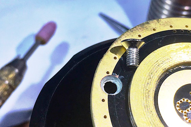
This is not the original screw.
I bought from the local store.
Only this M3 (flat head).
Yup, yup. ![]()
Yeah tail assy PCB.
Haven’t got to the springs or traces yet. Already thinkit improved.
I got 1 more in today, so I got 4 now - I'm frustrated cause I don't have the time I want to spend on them, but the tail PCB is a source of lots of lost amps. Just hard to see or say exactly what it is. I seem to get a small bump just from Nyogel on the main threads, and I've seen this before.
The screws mounting the tailboard to the tube are the - path, right? That’s the case in srk bodies I have with tubes anodized on the end faces where the tailboard makes contact. If the Q8 is the same, the conductivity of the screw material and actual surface contact % between the screw and tube threads would affect current flow and introduce an unpredictable voltage drop.
inside the tube where the tailboard touches the tube is bare, no anodize. The screw pressure assures contact between the tube and board surface.
Part of the problem with the glue on the screw threads is it pushed out on mine between the surfaces reducing the contact.
I cleaned the threads out and screw threads, cleaned the surfaces too. While not measured, I believe it helped some.
Anyone notice the raised brass ring is slightly cupped. I can see why the solder blob cells do well in this light.
I am using HG2 flat tops and they work fine with the slightly raised top, but the contact patch is smaller than a soldered 30Q would be. Think I’m gonna solder a set of 30Q’s for it next.
I kept the dual springs and used bare 22AWG to bypass into the through holes. Did not remove spring to do it. Also sanded off the red from traces on the backside added some solder on top of the traces, prolly not needed as the dual sided traces are best I have seen in width and well thought out tracks.


I care about efficiency in the highest modes.
Because it allows you tu run the max for longer. Your light can absorb only so many Watt-seconds before it gets too hot. I want it to push out as many lumen-seconds before this happens.
This does not mean that I don’t want top amps. But rather that I want the most capable LEDs out there, which bring fair efficiency even when driven hard. ![]()
I'm surprised to hear there was glue there. Maybe I missed it on mine or wasn't there - was it clear in color? Might explain to me why one of my light's battery tube did worse than the others.
Something was there on all 4 screws. May have been clear originally. Pretty certain it wasn’t Loctite (didn’t turn to white powder and wasn’t real hard) so I just called it glue. M2.5 tap cleaned the glue and anodize up.
2 M3 screws on the driver were clean, dry, not glued.