Rev4 19mm board for my shorty L2M finally arrived. Less then 3 weeks to Indonesia is fast enough. When inspecting the board, I realized that the led position is near the edge of the board which mean led almost underneath the tailcap body. So I think it will need led with larger emitting area to spread the light more, using 1206 smd led instead of 0805. The led pad is designed for 0805, have to solder at the edge of the pad to fit 1206.
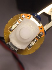
Using 1206 smd in red and 2K resistor.
Bright enough and apparently the light is spread nicely. The interior of Solarforce tailcap is bare alumunium (not anodized), kind of reflective. So with the combination of bigger led and reflective tailcap interior, this is the result.
Warning, the following paragraph is a little bit of a rant, but I need to get it out of my system.
I spent a night and the better part of a day working on my Astrolux lighted switch in my JAXMAN E2L flashlight. I didn’t like that it only came with 1 LED, but it was better than a non-lighted switch. I spent a lot of effort previously figuring out how to make it work with the FET + 7135 driver, please see here: D.I.Y. Illuminated tailcap. It was not a plug and play enhancement. Eventually the switch went bad (the flashlight started to flicker) so I needed to replace it with an Omten 1288. I also wanted to replace the LED so I bought an assortment of 0805 SMD resistors and LEDs. I thought it would be nice to have a green and a yellow LED on the switch. Seemed pretty simple, right? NO, NO, NO. The 2 LEDs have different forward voltages, so 1 was brighter than the other. So I switched to both being blue. I got the LEDs attached, experimented with different resistors to get the brightness (i.e. parasitic current) that I wanted, and replaced the switch. Everything seemed fine. Right? What could go wrong? I now have LEDs on both sides, nice and even. I put the switch back into the flashlight and nothing! It would not turn on. Did I put the switch on backwards? That is not even possible after I thought about it for awhile. Maybe the LEDs need to be turned around? So I did just that. Turned 1 LED the other direction and retried. Turned the other LED the other direction and retried. I kept experimenting. Then it dawned upon me that perhaps it was due to the new resistance/current of the switch that was causing problems with the driver. DING, DING, DING. So I tried a resistor that made the LED brighter, similar to the original brightness, and put everything back together. Seemed to work fine, but then the switch started to blink and the flashlight turned into next mode memory. So I tried an even lower resistor value. Everything seemed fine, yay! But then after about 30 minutes, the same thing happened. Argh! Finally, I figured, let’s try the original switch LED and resistor value. After all, it worked previously. And sure enough, that worked!
LESSON LEARNED, when working with lighted switches, it appears you must choose the switch LEDs and resistance AND then determine the value of the driver bleeder resistor, NOT the other way around. In order to use the new switch LEDs, I would need to change the bleeder resistor. I really don’t feel like taking apart the flashlight head, especially the way I soldered the resistor to the retaining ring. Maybe someday, but right now I’m glad to have my JAXMAN back, the lighted switch still looks good, and at least the new switch was successful.
Here’s what I was shooting for:
Here’s what I reverted back to (notice the same resistor value, but twice the current):
It took you just a night and a day to figure that out? Then you did well, I admire your steep learning curve. It took me longer to learn all that. Nothing is easy with lighted tailcaps, everything depends on everything.
NF you were persistent and got it working, good work. Clean too. :+1:
Your yellow version Astrolux board is different than I have seen so far with single LED.
Mine have a different look and came with 2 LEDs and 2 individual 15K (18C) resistors one on each LED path. These I bought separately off BG. I have installed a few if these into the EE X2R without any driver resistor mods.
I also have a black BLF version that has one LED and completely different paths that my Yellow. Yet it does have 2 paths on either side of the SW, they seem to be linked at each pad corresponding to the other side. Some light also came withe the black board ( BLF DL036_K6) bare no lighting on them.
Your Yellow seems like the Black ones I have as you can use one resistor to both LEDs.
For those that are interested, Banggood is apparently now selling the Astrolux lighted switch with 2 LEDs. I asked them about this when I started having problems with my switch and they confirmed that their new stock has 2 LEDs. There are numerous complaints on their website about receiving the switch with only 1 LED. Even their title now states 2 LEDs: “Astrolux SC/SS BLF X5/X6 Flashlight 2LED Lighting Switch For DIY”. I’m tempted to try it out with my JAXMAN, but I think there is a very low chance that it would match up with the driver. But, I should get 1 anyways for my next mod.
I finally got around to measuring the current of the lighted tailcap in my JAXMAN E2L flashlight. I was concerned about the 1.46mA that I measured with just a battery (#1585 ). That seemed rather high compared to what others have reported here. The tailcap does not seem that extra bright, it actually seems just about right. So I removed the flashlight head, connected a wire between the battery and the driver spring, and stuck my DMM between the driver retaining ring and the battery tube. I measured 0.51mA – much better!
BTW, I ordered the Austrolux lighted switch with 2 LEDs. I’m hoping that since my current and the new switch are both specified to work with the driver in the BLF X6/X5 and Astrolux SC/SS/S2/S3 flashlights, the new switch should also work in my E2L. I’ll report back once I’ve tested it.
The new Austrolux lighted switch came today and I immediately tested it with my JAXMAN E2L flashlight. And guess what? It didn’t quite work. The switch did come with 2 LEDs (and 2 1K ohm resistors), so that’s good, and the brightness seemed about right. With the flashlight on, the mode switching works great. The issue is that when I turn it off it does not revert back to the lowest mode, but instead only goes back to the next lower mode like a medium press. So rather than being complacent with my working 1 LED switch, I’m going to start over from scratch. I’m up for the challenge!
Is this where (circled in green) I can put an SMD 0805 bleeder resistor on my FET + 7135 Mountain Electronics 17DDm driver? As you may recall, on the right is where the resistor currently resides (not pretty :person_facepalming: ).
Thanks for letting us know about your experience with the BG lighted tailcap. I definitely want to try adding a lighted tail switch to a couple lights, but I don’t think my current equipment or skill set would allow me to build one myself. So I have been holding back on trying the BG one because I read somewhere here they were only 1 LED at some point. It’s nice to know they have 2 now.
Here’s the latest Banggood Astrolux lighted switch. Not a bad deal considering 2 LEDs and a double spring. It still looks like a no-brand switch, which I will be replacing with a Omten 1288.
Does anybody know if this is where (circled in green) I should put the bleeder resistor on a my FET + 7135 Mountain Electronics 17DDm driver? Sorry to bug about this again, but I’m getting ready to start experimenting with different values and don’t want to screw up the driver. Here’s another picture that hopefully is clearer. Thanks to anyone that can help.
No, those pads wouldn’t be a good spot for the bleeder resistor… if you could even make one fit. Those pads are tiny
It needs a bleeder from BAT- to BAT+. From the outer contact ring to the inner wire hole, somehow. I don’t see an easy way to do that at the moment, but perhaps it’d be easier on the spring side? Or perhaps from the center hole to the 7135’s middle pin if you can do it without touching either of the other pins)?
If you have a floating resistor with wires on either end, it might be easier.
Like TK said, I find it easier to do on the spring side of those drivers. I scrape off a little solder mask from the large area and solder it there (click to see larger image)
Thank you TK and gchart. Agreed that there doesn’t look like there’s any place on the component side for a bleeder resistor.
So I tried different resistors on the spring side. First I tried a 680 ohm resistor and got the same result as the 328 ohm resistor. Then I tried a 220 ohm resistor and BAM, SUCCESS! Here’s my set-up. I didn’t want to put everything together to test each resistor, so I wired it up manually.
It was a challenge to stretch the solder from the spring to the resistor and the resistor to the retaining ring, but eventually I got it to work. To clean things up, I put the driver onto a drill and sanded down the solder that went onto the retainer ring.
I kept the 2K resistor on the switch and replaced the original LED with 2 0805 blue LEDs. I measured 0.56 mA for the tailcap.
It looked fine before, but now that it has 2 LEDs it looks so much better. I feel proud that I was able to make this work.
That looks really nice. It’s good to know you solved the problem. This will be helpful for when I start taking baby steps to learn how to light up a switch. From what I have read so far, people have different methods for soldering the tiny components. When you added that resistor to the driver spring side, and replaced the switch LEDs, did you use an iron or hot air, or something else?