[quote]
Its odd that even after screw cutting hundreds of threads I still get nervous that something will go wrong.
[quote]
I get the same nerves with wood. Most often I get rewarded with a nice fit, good finish… . Other times… :person_facepalming:
[quote]
Its odd that even after screw cutting hundreds of threads I still get nervous that something will go wrong.
[quote]
I get the same nerves with wood. Most often I get rewarded with a nice fit, good finish… . Other times… :person_facepalming:
This weeks update is more about failures than moving ahead.
Trying to hasten the speed of the build up a bit I spent an hour or so in the evenings after work each night in the shed.
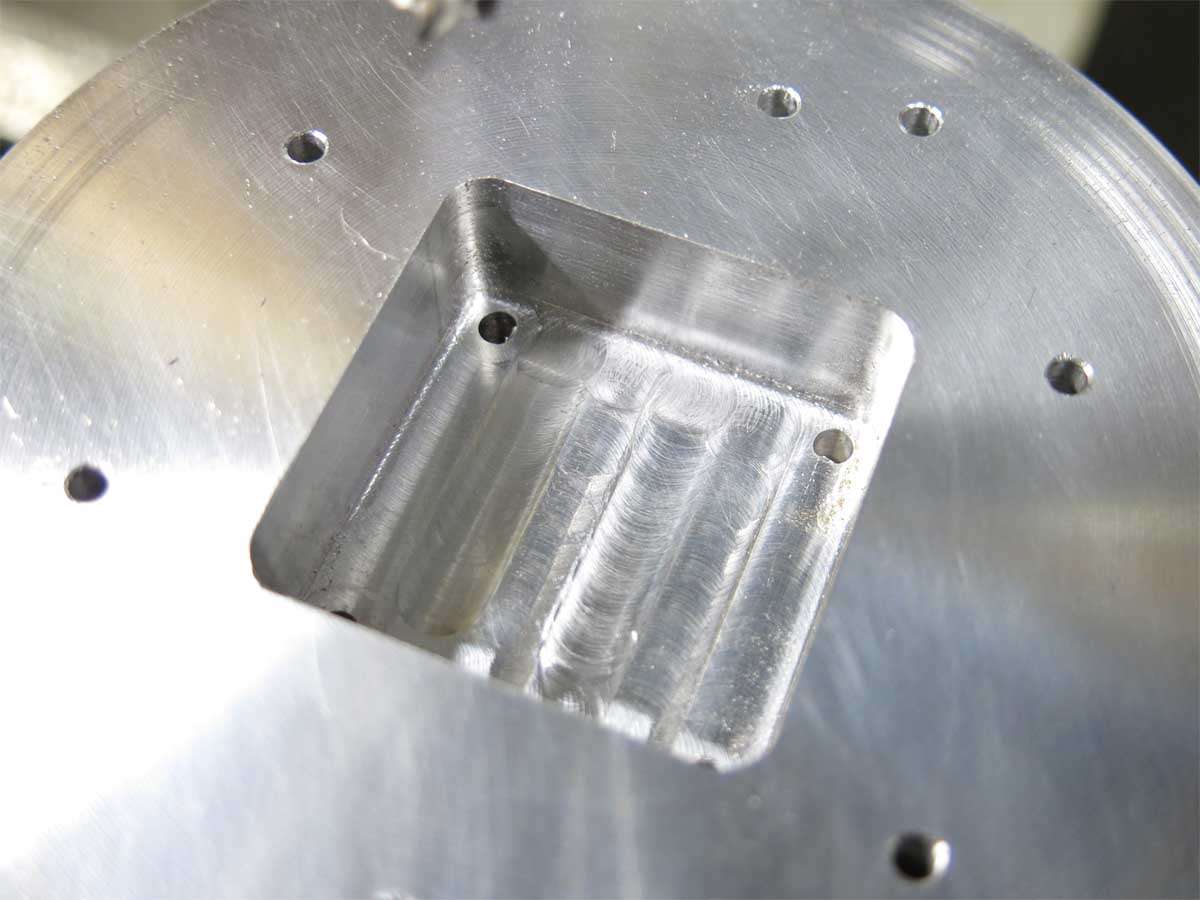
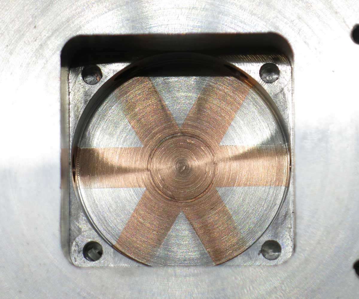
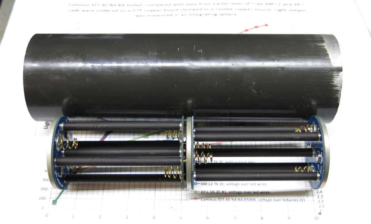
Work started on the part that will house the fan on one side and the leds on the other.
The aluminium here is about 110mm in diameter and 44.5mm in width.
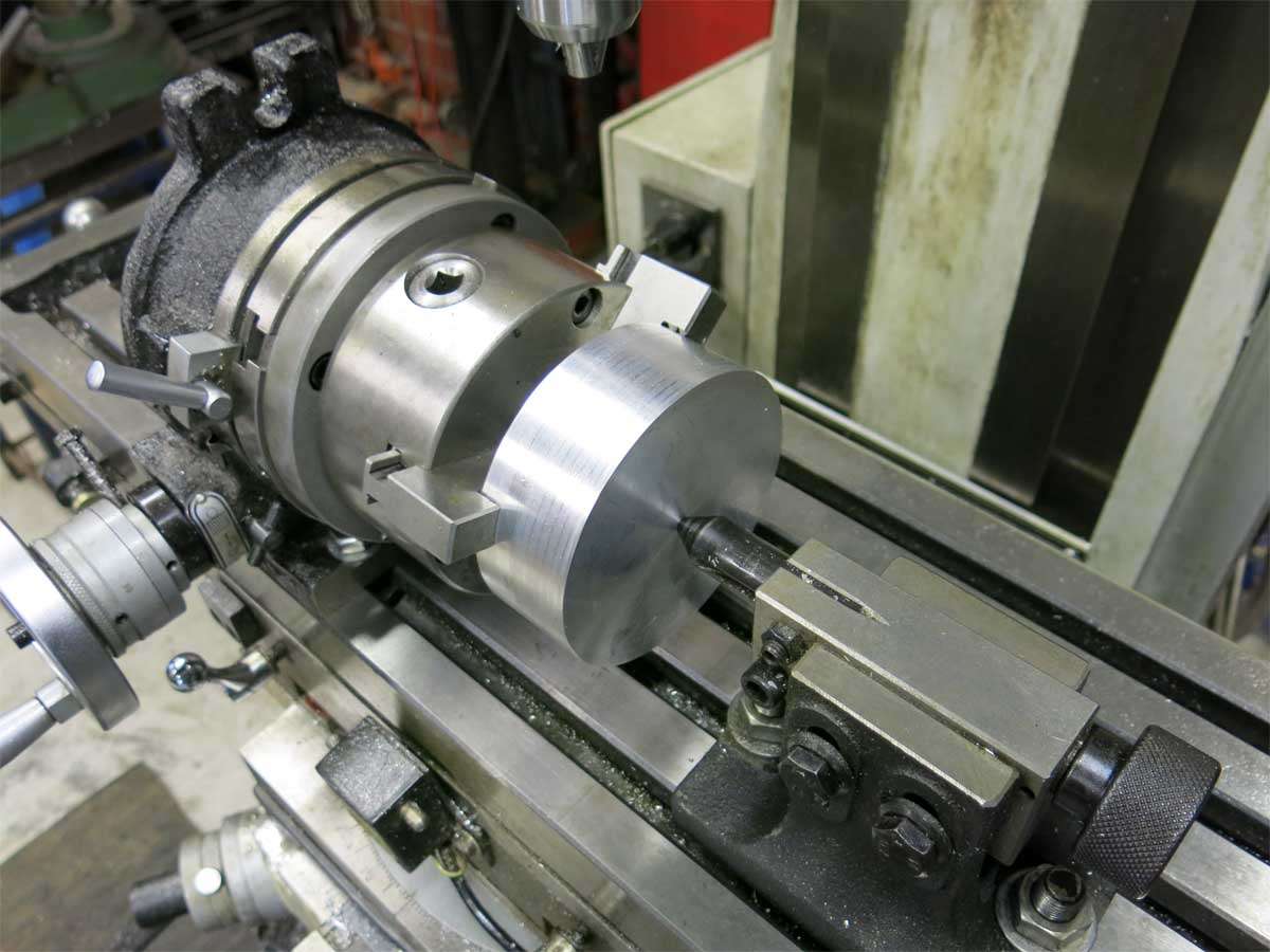
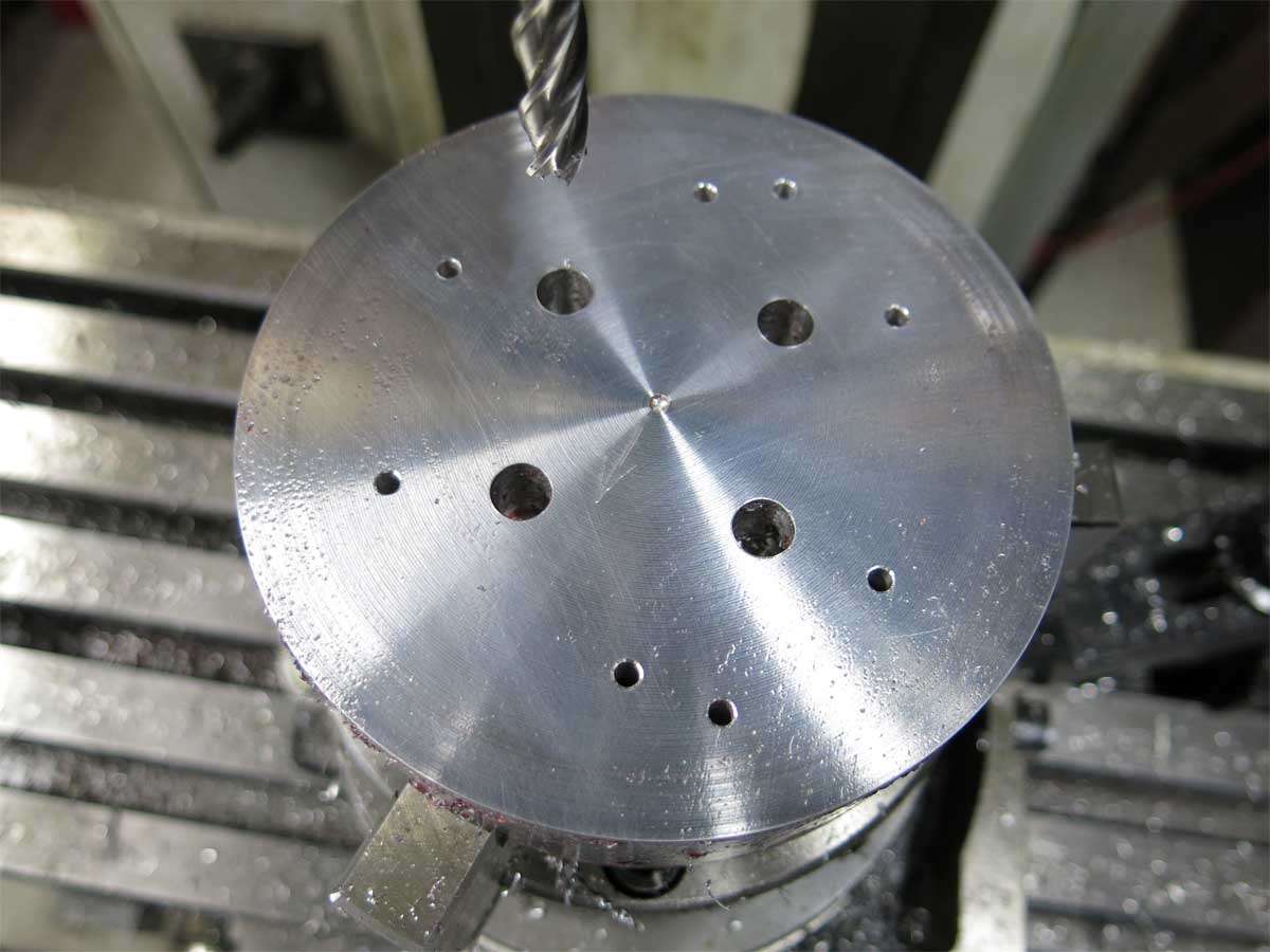
3 x 3/8’’ holes were drilled spaced at 60 degrees.
This allowed 3/8’’ copper bar to be inserted through the aluminium.
Long story short, I drilled two of the 1/8’’ through holes in the wrong spot. Wrong PCD.
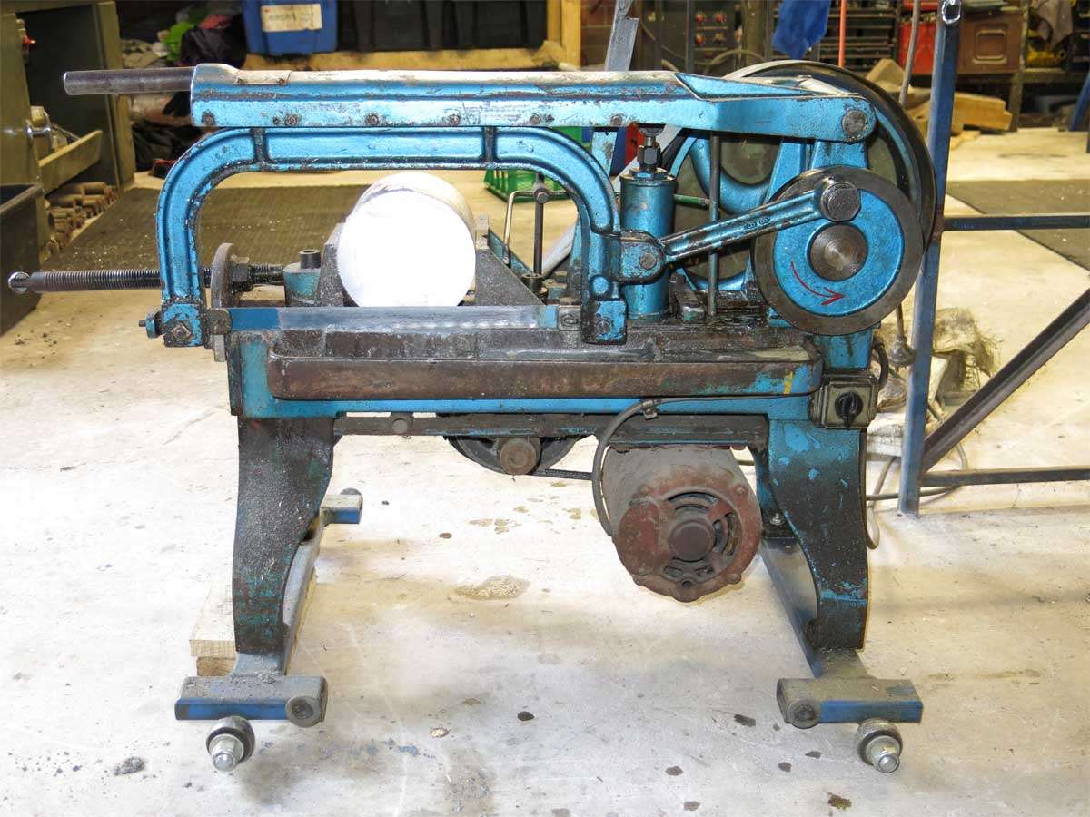
Starting again I only had 150mm diameter aluminium bar so this was cut to length in the older than I power hacksaw.
On knocking the copper rod through the holes on the second one, the copper picked up internally and butchered the aluminium.
The third one I managed to get the copper through ok.
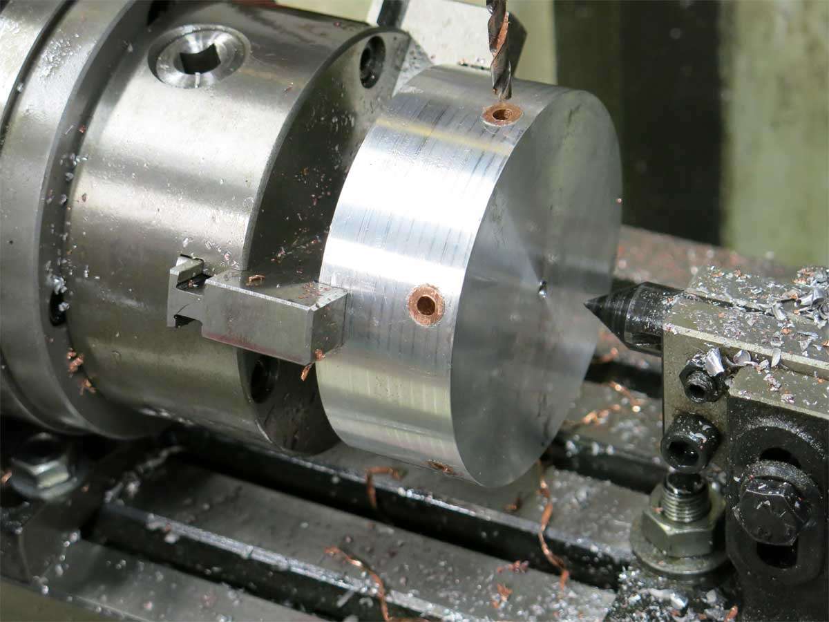
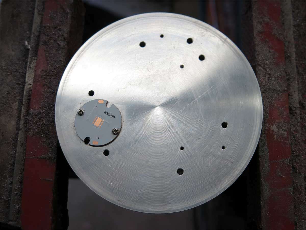
Lots of holes were drilled and the MCPCB bolt holes were tapped M2 and yes I snapped a tap of in one of the holes. I really will have to get the correct drill for this size tap. Luckily for me it wont matter as the MCPCB’s will also be held down with the reflectors.
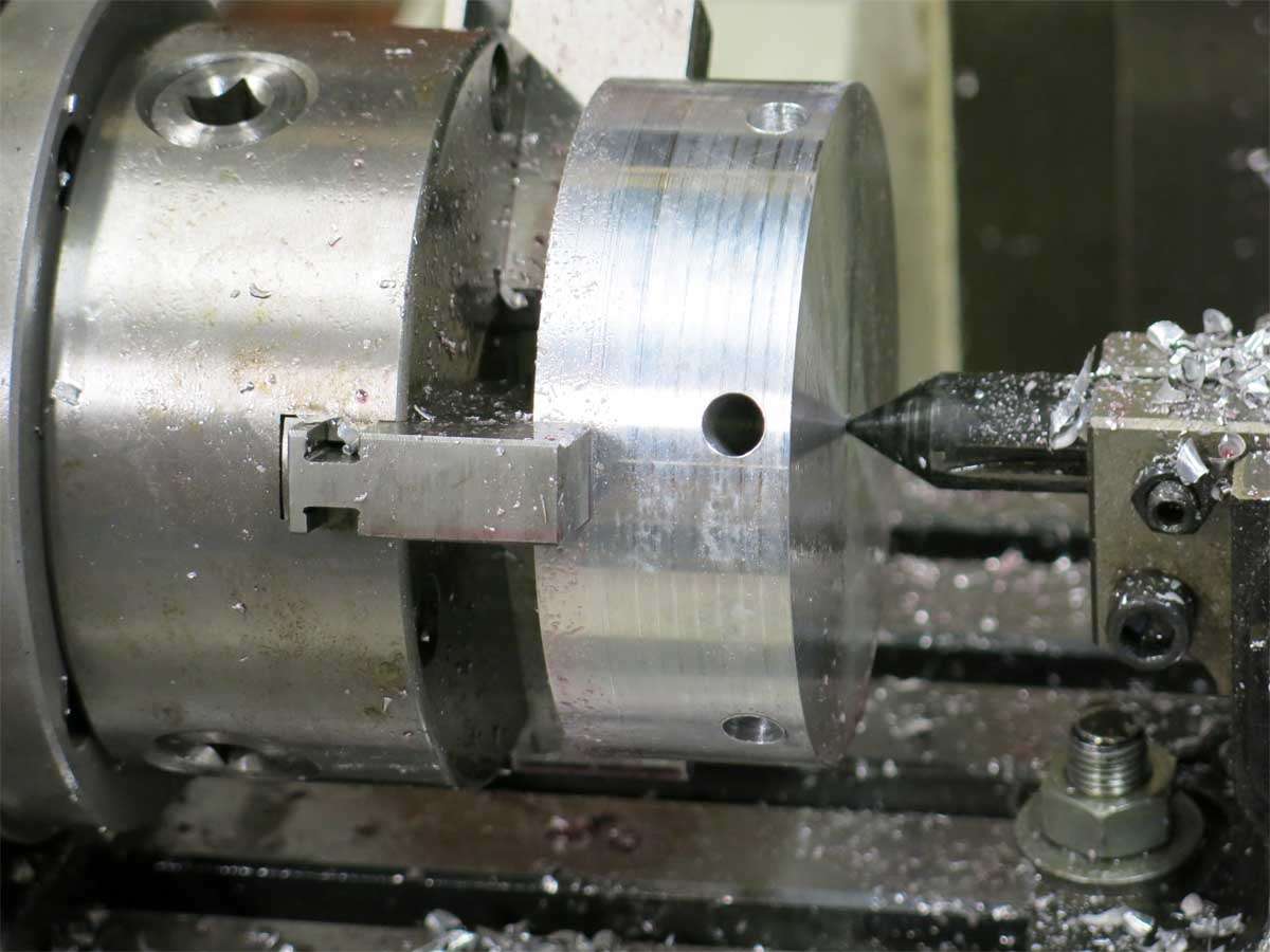
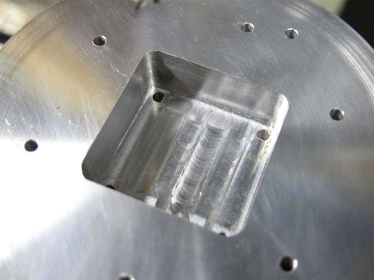
Six 1/8’’ holes are through holes that will let the cap screws pass through from the reflector part with the reflector threads in it, through this section end up screwing into the next section which will hold the driver.
The two random holes are to allow the power wires to feed through to power the leds.
The four large holes here are for the fan cavity.
And a moat appeared.
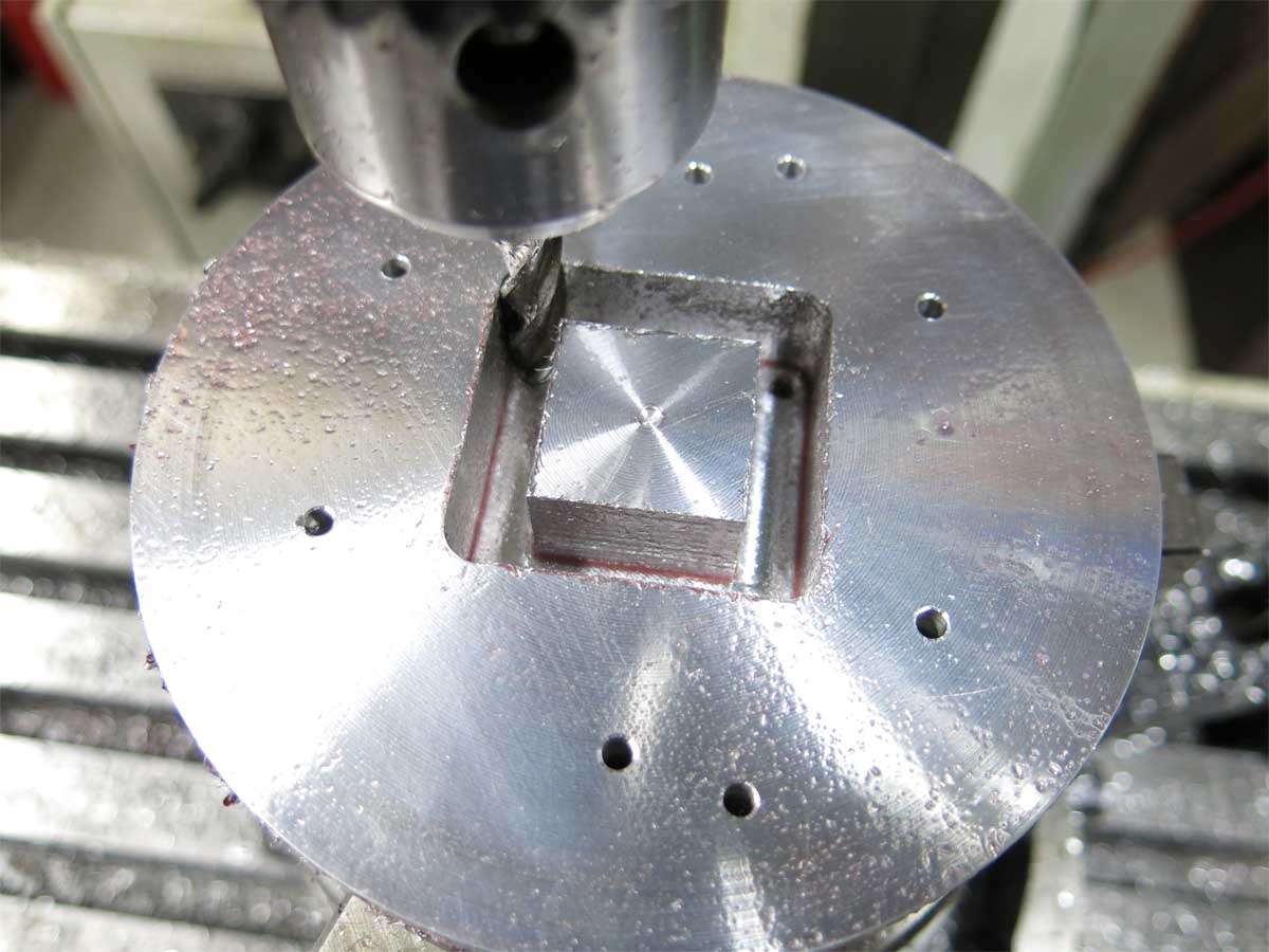
The through holes for the cooling are yet to be machined.
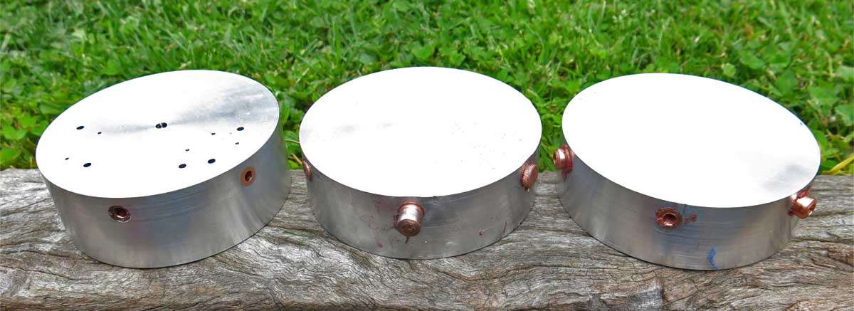
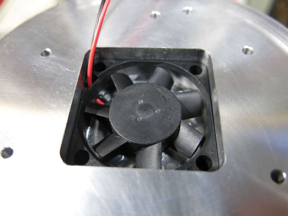
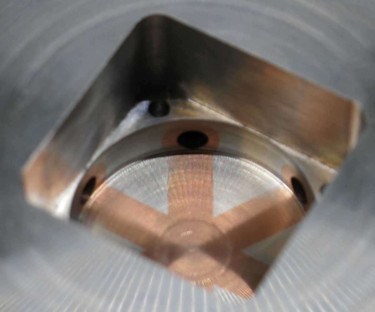
And finally the fan in its new home, temporarily at least.
Third time lucky, cool ![]() :+1:
:+1:
I’m glad to see you had perseverance. And enough aluminum stock at hand. ![]()
I realised while asleep last night that I need a 12V fan, not 5V. I hope I can find one in the size the hole is.
Nicely progressing ![]()
If you don’t mind, I’m going to take small comfort in knowing that someone else’s fails were more expensive than my fails :zipper_mouth_face:
Thanks FmC. The bills in the mail as the good wife wont pay this one. :+1: ![]()
On testing the fan it was found the more gap on the inlet side between the fan itself and obstruction above it the more air it moved. On this basis the hole recess was deepened further.
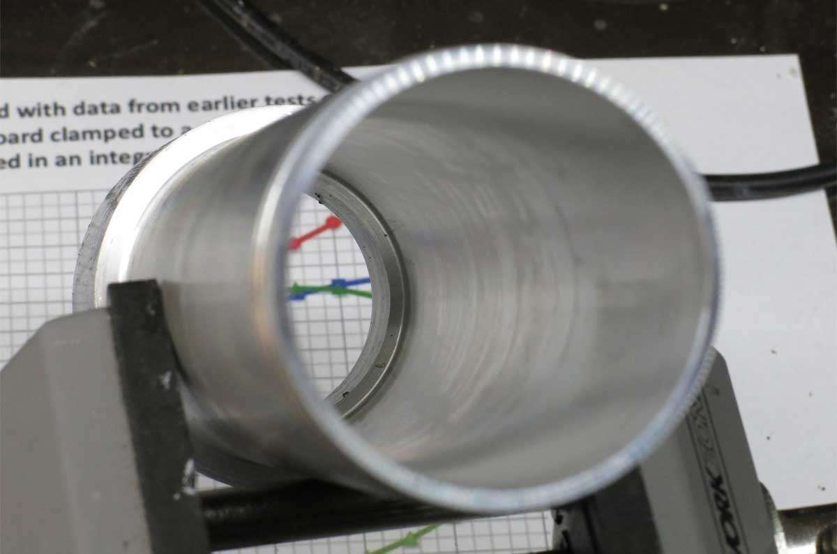
A hole was then milled out to 19mm in diamter through the copper heat tubes.
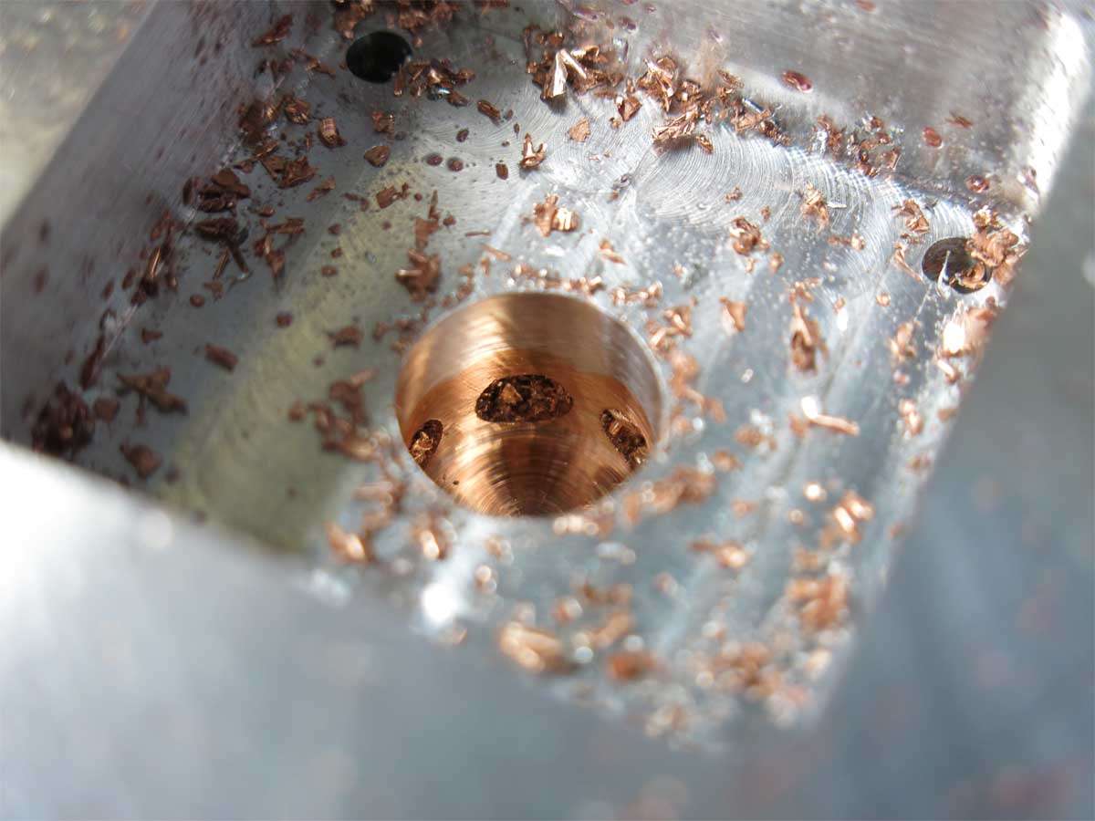
This was then machined out in the lathe.
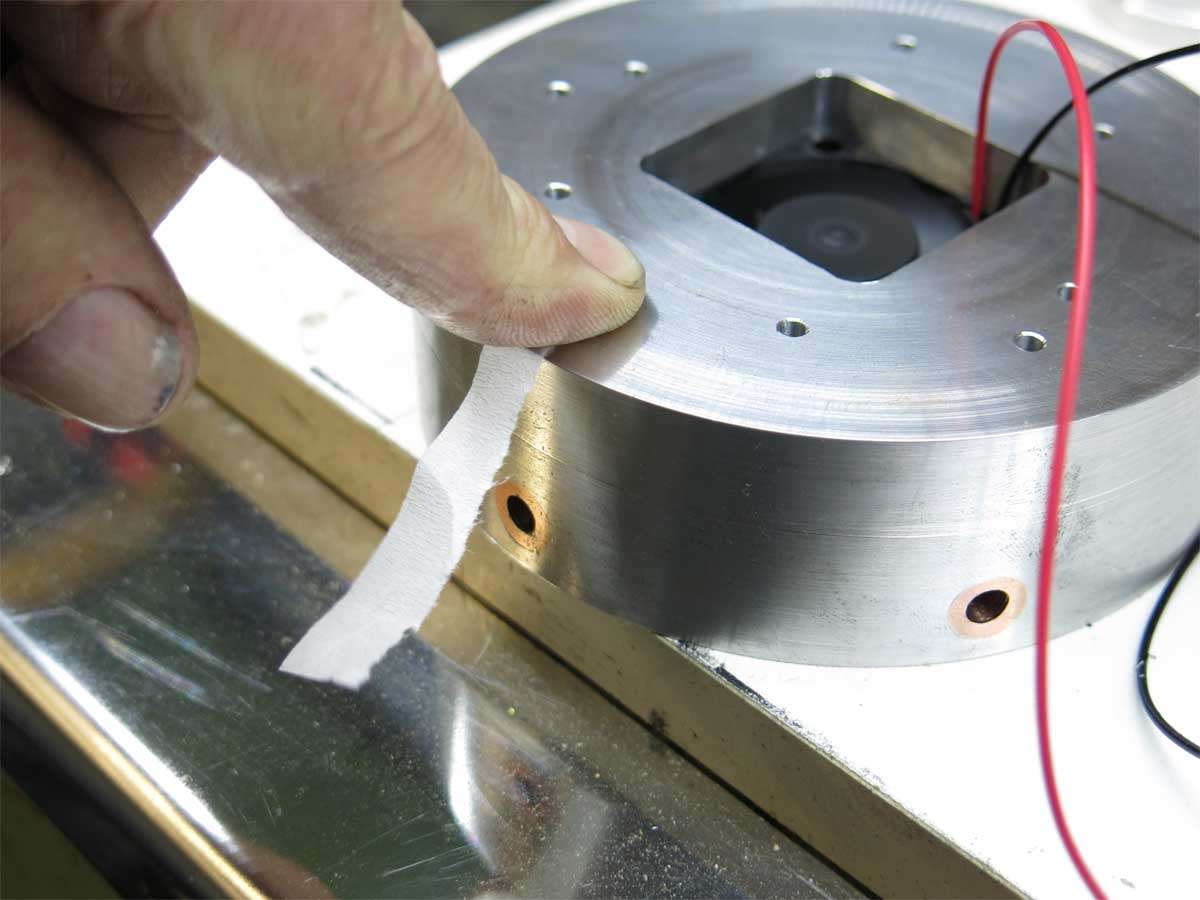
And a view of the heat tube holes where the air blows through under the leds.
I have no idea at all if this is going to cool very well in the light of reality but we shall soon find out.
The fan is in operation here blowing out a gail force wind, I wish. :person_facepalming:
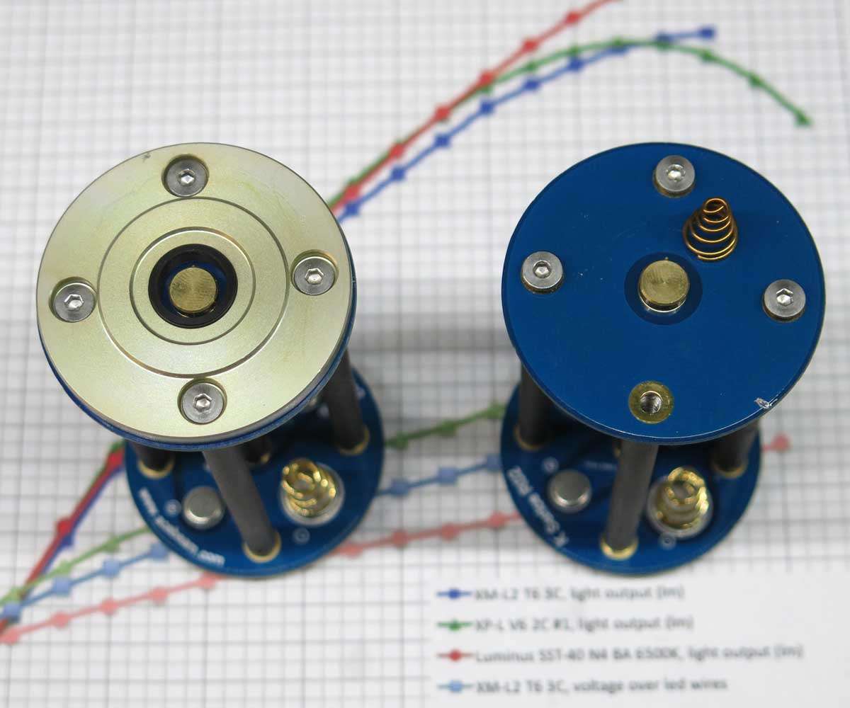
The next part on the agenda to be made is the battery tube.
The problem of battery holders was solved with a quick solution as time is rapidly running out. I had previously purchased in a group buy three battery holders which are 4S1P. I will be running two of these in parallel.
An old aluminium tailgate cylinder rod off cut was found to be around the right size.
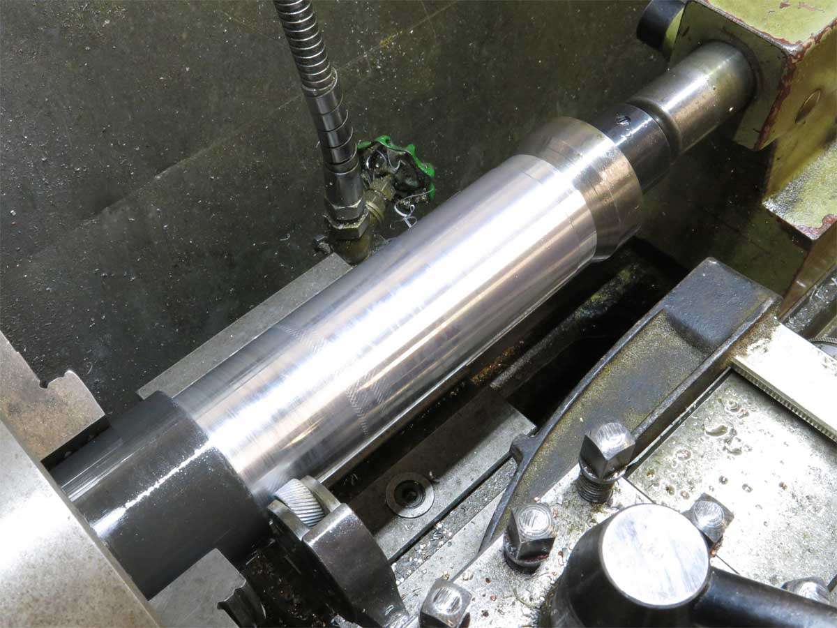
This was taken to work to rough it as it would of taken me a week to machine this out on my lathe where at work it was quickly machined out during my lunch break.
The big lathe at work board this depth easily without chatter.
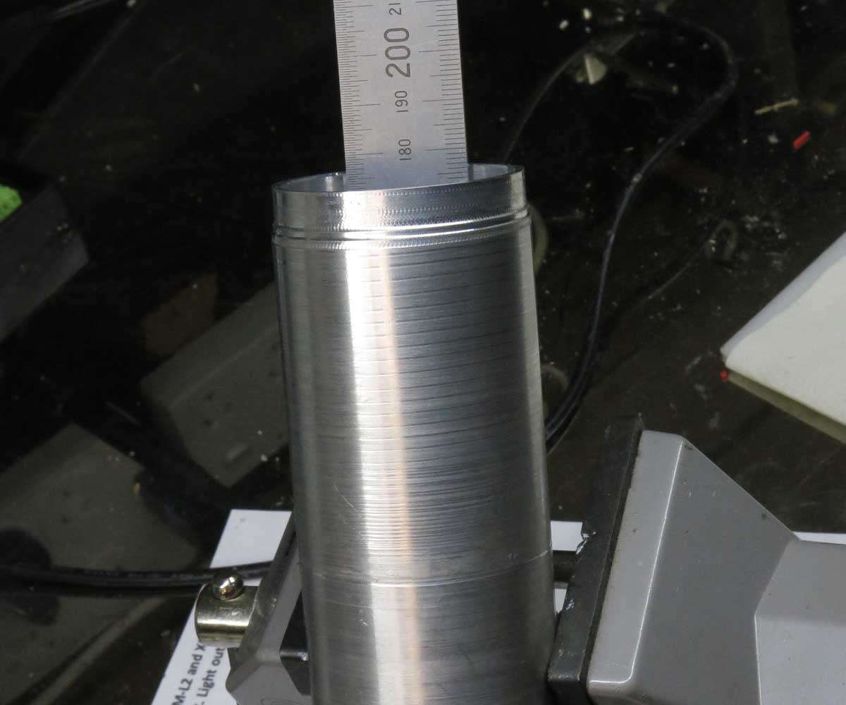
The rough outside was turned down to the same diameter as the Q8 battery tube and the knurling tool set up.
There is no drawing for this part as its just being made up on the go. The battery tube will be part of the naked design when its finished.
After a few anxious minutes which seemed at the time an eternity we had knurling.
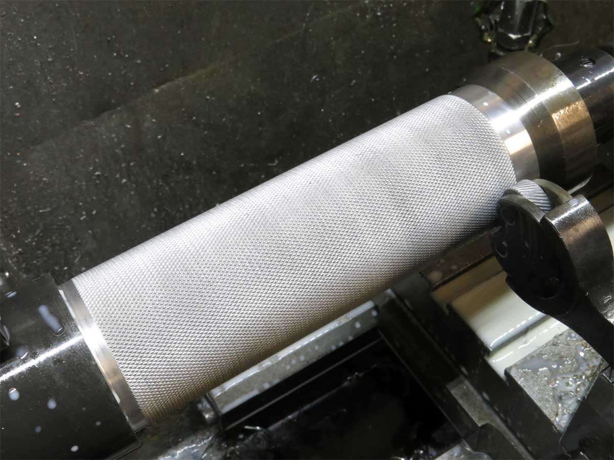
At this point if I still drank I would of put the beer down and had a Scotch. I hope someone out there has one for me. ![]()

You have quite a lot of aero resistance already. If you can, pick a high-pressure fan. Also, I would try positioning the fan higher, I have a hunch it would work better.
I would also suggest machining the fan hole slightly deeper and putting a small heatsink at the bottom to add some fin area.
SU-PER-B
I have a hunch that the fan would be more efficient (due to much less turbulence in the chamber) sucking though the holes than blowing though them.
The fan is what was available quick as there is a time limit on the build.
As for sucking rather than blowing I think it will work better blowing through the holes as the intakes will be a lot larger than the outlets. Then again maybe not. I’ll just get it together and if more work needs to be done I’ll worry about it then.
On a side note I may try and taper the sides of the recess on top of the fan for more of a venturi shape.
Looks great sofar!!! Following your work in awe again! ![]()
Sucking is better, always.
Man I miss this stuff, feels like im peering through a window at a party I can’t join. Toss one back for me too, will ya?
Lovely craftmanship :+1:
The air output vents would be best adding up to the air intake area, maybe larger or thereabouts I think, plus taking in considerations for right angled bends, reducings, friction etc, there are calculations for that type of thing I’m sure.
Of course I could be wrong about that as it’s not my field but it looks great.
Nice to see you RBD.
A good time to have a wee dram of the ever dwindling supply of Mortlach :+1: ![]()
Jusht won mor

Still sitting on the edge of my chair waiting ![]()
Cheers David
Thanks for the input Agro. I may come across a bit like that (agro) at times but dont mean to. ![]()
I’m always open to suggestions.
I may have to restrict the three holes that dont travel directly under the leds as they may end up shorter in the final shape of this block. My thinking is the shorter tubes will flow more air than the longer tubes travelling under the leds which I dont think will be good.
Good to see you dropped in for a visit RBD. You are sadly missed but then you do have a life away from here. ![]()
Looks like Don is about to throw that drink to you. Thanks Don.
Crx. Like your builds you have me lost, with your input. :person_facepalming: I’m just a simple Moose. ![]() RBD has spent a lot of time and effort explaining all sorts of topics around here to me and for some reason seems to understand the Moose’s inability to communicate better than lots of others, my wife included.
RBD has spent a lot of time and effort explaining all sorts of topics around here to me and for some reason seems to understand the Moose’s inability to communicate better than lots of others, my wife included. ![]()
We’re getting to the pointy-end :+1: Sorry, I can’t have a drink for you yet, as I’m about to head off for work :nerd_face:
Your build is really taking shape.
Yes, shorter tubes will flow more air. How much? I can’t tell.
Cooling strength is proportional too temperature delta * airflow * cooling area.
By closing the shorter tubes you put much more more airflow to where temperature delta is higher. But you get lower total airflow (not 4 times, but much lower nevertheless) and much lower area. Is it a good idea? I don’t know, but something tells me it’s not.
It will certainly be better initially as heat will arrive in that tube much earlier than in the others.
But as the block saturates with heat, there delta T will not be several times higher in one place than elsewhere.