Thanks!
Are they expensive to make?
Thanks!
Are they expensive to make?
You can buy 3 ring boards from Oshpark fro a little more than 2$ and you can buy the leds and resistors for cents on ebay.
LOL, accidentally fixed your joke for you. ![]()
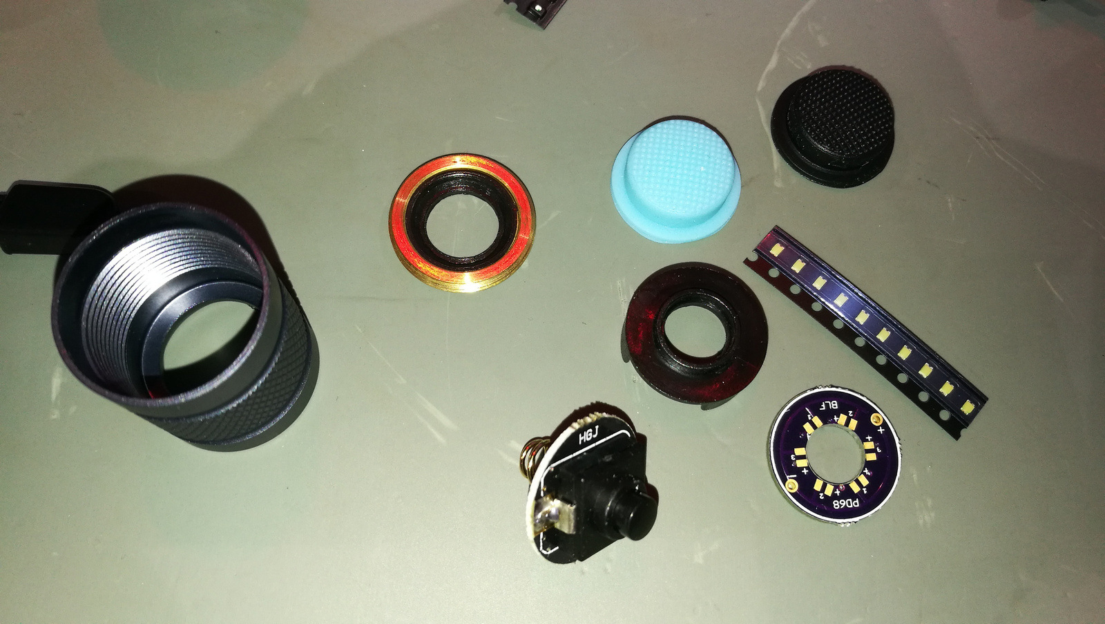
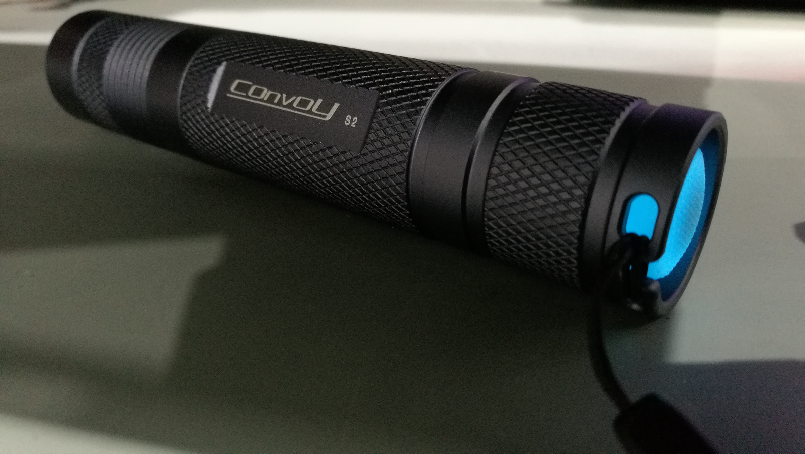
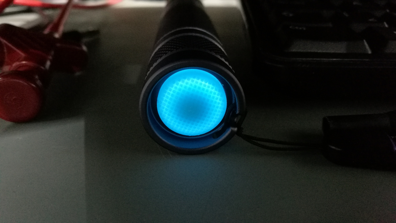
Today I finished the S2-S8 internals swap and added light blue lighted tailcap to the S2.
I removed 2 7135s of the 6 because 4 is enough for a 5 year old kid. The tailcap contains a big switch PD68 board and white leds. The rubber boot is a light blue from Simon’s aliexpress store.
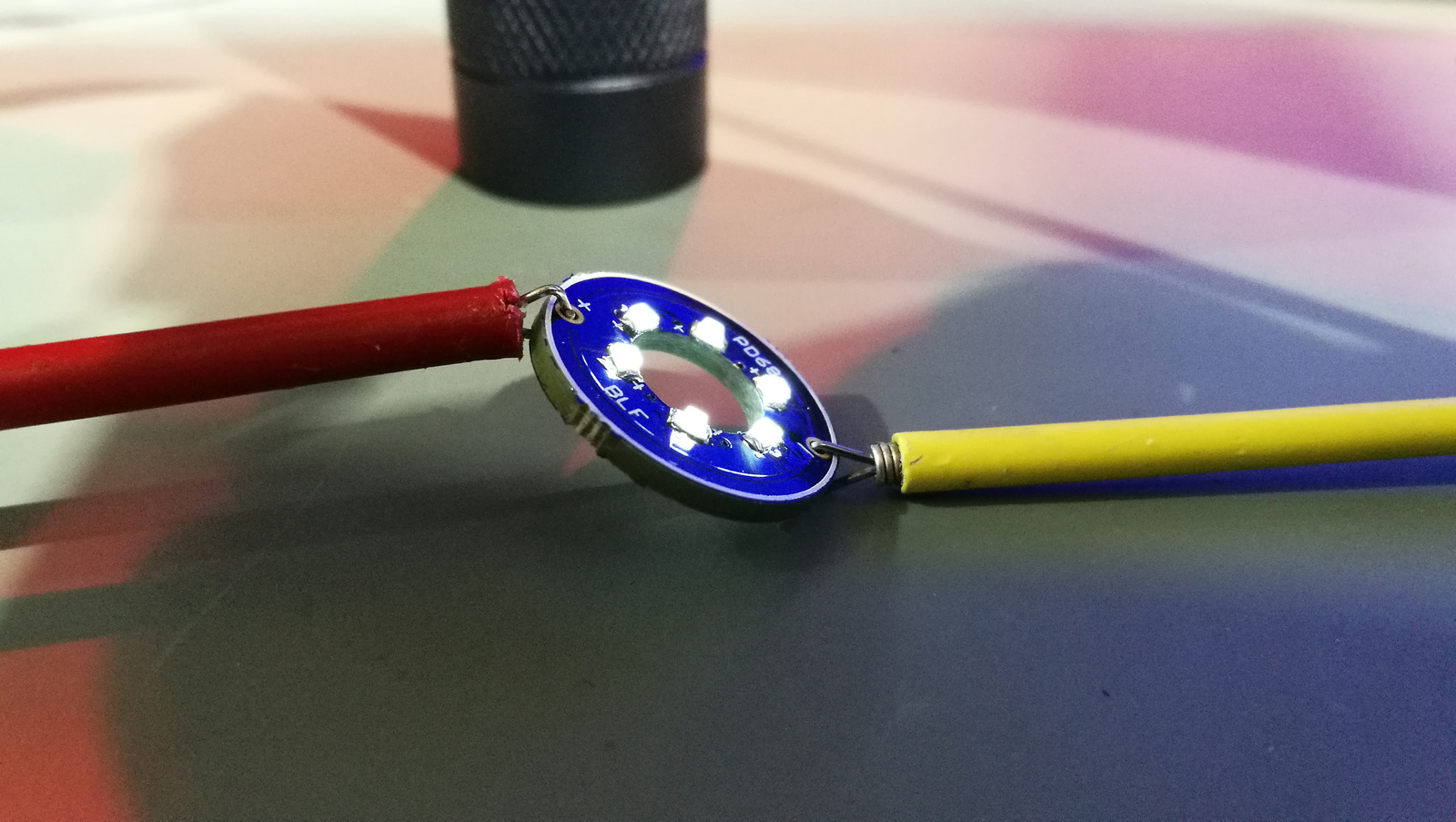
Can you show modification to the driver for blue taillight to work!
Sure!
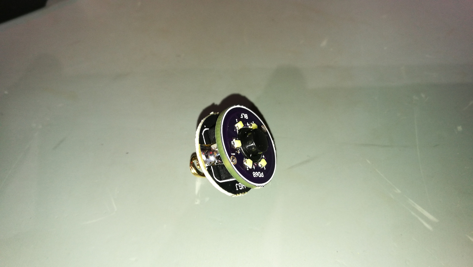
It has 10K resistors for each pair of led on the switch ring board and the driver has a 560 Ohm bleeder resistor soldered this way between the spring and the side ground ring of driver extended with a very tiny wire what you ant see in the soldering.
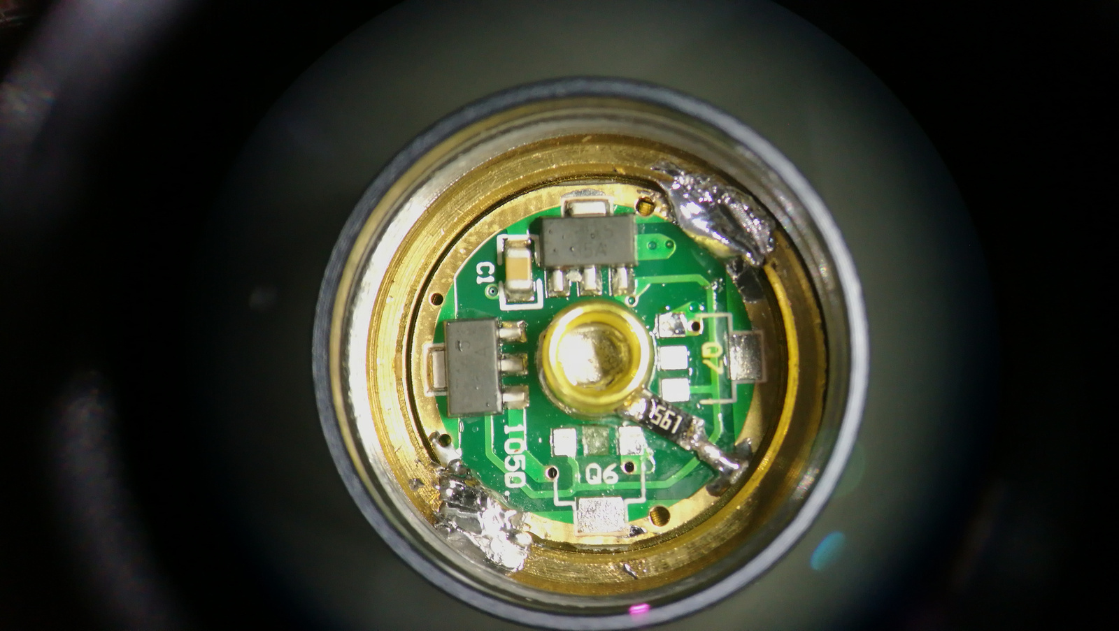
I know I ripped off the Q6 pad when removed the 7135 and cleaned with solder wick :person_facepalming:
Thanks, this is good info for beginners that want the same look but don’t know what they need to do to get that shiny new tail switch ![]()
![]()
Received a clear S2+ today from GB with the standard black tailcap.
Since i dislike the looks of a clear S2+ with a black switch i ordered a stainless switch to replace the black one.
Used some EPDM rubber to get a good grip on the old switch (and to avoid damaging) with the grip provided from the rubber it was very easy to unscrew it, inserted the new stainless one, and voila!
This is how it should be directly.
The lighted tailcap is a nice feature though, but way too dim!
Should fix that next.


Zozz, that center pad isn’t needed… the ground tab on the other side of the chip is doing the job. So in this case, you got off easy. Either way though, since you were removing the chips to downgrade power level none of those pads matter. You could have just as easily removed all the 7135’s from the spring side of the driver and if you wanted 6, stack the extra on the inside. ![]()
I bought a Nitecore “Night Officer” SRT6 with magnetic ring variable output a while back during a sale, the specs say the XM-L2 T6 does 0-930 lumens. This afternoon I pulled the thin aluminum mcpcb with the XM-L2 and fitted a 20mm SinkPAD to take it’s place, equipped with a Luminus SST-40 emitter.
I now see readings as low as 0.1035 lumens and as high as 1293.75 lumens, for simply changing out an LED. Nice! ![]()
That SRT6 always looked kind of fun. Same with the CU6. I was never able to justify the price though, since I have better smaller options for white lights and the color modes aren’t really useful for me. Still though, it’s a neat light that I’ve considered buying several times.
These days, I’m making my own RGBA stuff instead, since I found actual uses for the colors. I should probably stop procrastinating on that project…
Seems like I saw this SRT6 for some $34 and change, one of those bulk buy deals, sure wouldn’t have paid $100 for it. The dial up ring is nice though, SOS hard left, first click to the right is a Standby and a red light blinks letting you know it’s powered up. Then further turning it to the right is a click feel out of Standby and a smooth twist up to Turbo, then a click over to Strobe. So it’s easy to set it before turning it on, makes it very predictable what level you’re getting when you click the tail switch. Beam profile is nice as well, somewhat of a large hot spot with the domed XM-L2/SST-40 but it’s well defined and spill is soft but present.
Edit: Ok, wishful thinking. I DID get it on sale, but not that good a sale! I got it last November from Battery Junction for $25 off, so I paid $71 for it. I liked it better when I was remembering $34…. :confounded:
Yes, I appreciate your assistance ![]()
I wanted to make a wide-spectrum D4. Richard didn’t quite have the tints I wanted in stock though, so I made it a medium-spectrum light instead. I was going for 7A, 5A, 3A, and 1A… ish. Maybe a little variation at each step depending on what I could find. But instead I went with 5D, 3D, 3D, and 2B. And a frosted optic to help blend them.
The result is about 4700K and pinkish, very similar to a Nichia 219B emitter. The tint variation is certainly not as wide as I’d like, but the result looks pretty nice. I may have even over-done the pink a bit, but it’s not very noticeable unless it’s next to a D4-219c with its rather not-pink 5000K tint. Perhaps one of the 3D emitters should be 3C. Or perhaps a wider tint spread would look nicer. But it’s pretty close.
Of course, while it was open I also updated the firmware to the latest Anduril. Compared to stock, it adds a bunch of modes and UI tweaks and makes moon use a fraction as much power.
It’d be nice if they could be purchased like this.
It would be nice, wouldn’t it?
I flashed Anduril to my D4 as well, the green XP-E4 emitters really heat up at full Turbo so it’s nice to be able to limit ceiling on ramping. The green color washes out quite a lot at full power.
I had the D4 and D1 side by side on the shelf, tail standing, doing a green and white lightning display. lol Do you think I could start em simultaneously and have a matching lightning show? The dual random thing got a bit much in the green/white display… hahaha
Emisar D4 Beacon/Indicator/Extreme-Moonlight-Mod
After adding switch LED support to my Q8 momentary firmware I wanted something similar for my Emisar D4. Instead of using real switch LEDs I decided to use the ordinary front LEDs. PWMing them would prevent sleep mode of mcu, so I soldered two 10k SMD resistors in parallel (=5K) and wired them between LED- and PIN 3 of mcu (don’t have 4.7k currently). With low level at PIN 3 the front LEDs are powered with a current of about 360 uA (Nichia 219C).
I made the indicator function configurable with a specific click combination and have 3 options now:
1.) No indicator function at all,
2.) When off LEDs are glowing, when locked out LEDs are off,
3.) When off LEDs are glowing, when locked out there is a short flash each 4 seconds.
Power consumption in lockout mode with flashing LEDs: less than 60 uAh, the light could run for several years in this mode.
Lockout mode may also serve as a long lasting beacon, and off mode as a really low moonlight.
You find the 2x10k resistor stack at the left of the 7135:
Resistor stack fixed and isolated with Arctic Alumina:
Flashy Mike, great idea!
Nice indicator function :+1:
I rebuilt my triple 219c Maratac CR123 tail clicky today with a better switch and a Nangj 105c 3A driver

.
And replaced the battery in my 4yo electric toothbrush with an eneloop, much better now it doesn’t cut out unexpectedly half way through ![]()

Nice work, both of you’s! ![]()
CRX, I like how that Maratac looks like an 8 shot revolver cylinder. lol
What? No light on the toothbrush? Geez! Nice save….
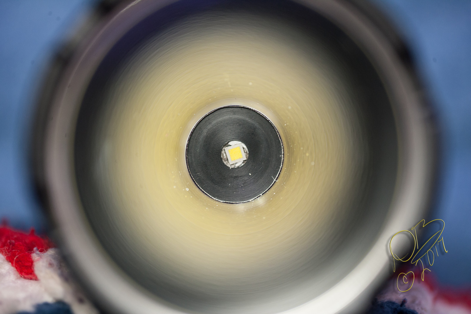
I had previously done some work on my Klarus G35 right before I had surgery, removed the flat at the bottom of the reflector and made a Delrin cup to act as centering ring. Yesterday I removed the HD XHP-35 and put an HI E2 3D in it. The overall reflector height was leaving a bit of a shadow in the middle of the hot spot so today I flamed the head until I could get the glue broken loose and unscrewed it from the pill section enough to seat the bezel completely and now the hot spot is clean. I lost a few lumens in the trade but took candela from 223.5Kcd to 281.5Kcd, from 945.52M throw to 1061.13M. All in all it was worth the effort to fine tune it. ![]()
It took about an 1/8” backing the head off to allow the bezel to seat properly and attain focus, you can see here that the flat area at the base of the head is now well clear of the switch platform, where it had overlapped slightly in stock set-up…

And the HI emitter, from enough distance to show the reflector getting the square domeless emitter…