I believe TomE has some experience with thermal analysis of flashlights. Maybe he could tell something about the expected temperature deltas?
nice steve keep the updates coming
Some very basic preliminary tests which will be repeated when I have time to double check the first tests were correct.
With a single MTG2 mounted and run at 20 watts the temp stabilised at 45 degrees C with the air sucking through the tubes. With the fan blowing through the tubes the temp stabilised at 38 degrees C.
I have a feeling my fan will not flow enough air as this light will run around 60 watts with the leds picked and the fan will never see a full 12 volts which it was run at for testing.
Larger holes through the copper may help as it will restrict air flow less and give a larger area for the air to work on.
Surprise.
I just checked my sources, they agree with what I knew, sucking should be better…Anyway, it’s good that you tested.
I appreciate the input Agro.
Maybe its the size of the holes in the tubes that are just restricting to much?
I should of also mentioned that I severely restricted without blocking three of the six tubes so more airflow would travel out the tubes under the leds and the temp rose.
You have 2 sides, on 1 you have higher resistance, on the other you have lower. On the high-resistance side you create either positive or negative pressure.
Regardless of actual resistance and pressure values, positive pressure is expected to cause more turbulences and lower airflow.
Maybe the turbulences actually increase the airflow directly next to the fan cavity surface and enable better capture of heat from that place?
Beats a finite element analysis :+1:
I’m sorry for offering another piece of unsolicited advice (this project is so cool i couldn’t help) but there might be a possibility to multiply the dissipation surface area if you did some grooves on the back side of the “pill” and covered it with a sheet of aluminium to force the sucked air to go though it, did some painstaking modeling in solidwork to illustrate the idea:


Air would be forced through where the red arrows point
Your on the money jamesb
Surface area is king even doubling the number
Of holes and leaving the copper tubes out would
improve things.
The copper though looks pretty and adds significantly
to the frustration of the build.
Thanks for trying different ideas steve.
Where you have drawn the black lines James and they finish on the sides will either be a slot or series of holes for the air to pass through. I haven’t started this yet as I have to do the grooves for wiring to travel through which I’m not sure where that will be until the section for the driver is completed. This will be the final piece to do.
That would look quite smart, along with the functionality.
Draw the incoming air through the evaporating CO2 from a piece of dry ice. :smiling_imp:
I was contemplating doing this very thing but knew you wanted to do it in your comp build so dropped it. ![]()
Actually I contemplated using water cooling and then using the steam from the boiling water to drive a turbine to spin an alternator and recharge the cells. :person_facepalming: But that was too close to FmC’s entry.
I don’t know how smooth the inside of the copper pipes are but if they are smooth you could be suffering from stratification, run a tap through them to create disturbance in the airflow to reduce the effects and improve cooling ![]()
This will also increase the surface area more than drilling the hole bigger.
Cheers David
Really interesting to see what you end up doing with the cooling, Steve. Hope you can sort it out.
Oh - that would have been great to see that. Sorry you thought it was too similar to my build.
A mod and lots of testing was carried out today. l’ll post the results up when I get some more built.
Bathurst is getting in the way this weekend.
Some more heat testing was carried out after drilling the copper heat tubes out from 5.1mm to 6.35mm.
with an ambient temp of 11 degrees C and 21 watts of heat generated the head temp reached 51 degrees C. With the fan running of 8 volts temp dropped to 34 degrees C.
Raising the wattage to 43, two leds running at 5.5 amps, the temp of the head stabilised at 68.5 degrees C. With the fan switched on temp dropped to 43 degrees C.
Machining wise a lot of repeats have been happening. I’ll explain as we travel through this post.
New ends for the battery holders were machined up at three mm in thickness. I was not happy with the way they worked with the springs so they were remade five mm in thickness and new springs soldered to the opposite ends of the battery tubes.
A comparison with the new end against the OEM end.
The head was drawn up napkin style shown here with all the components going into the head.
And the head machined to what was drawn.
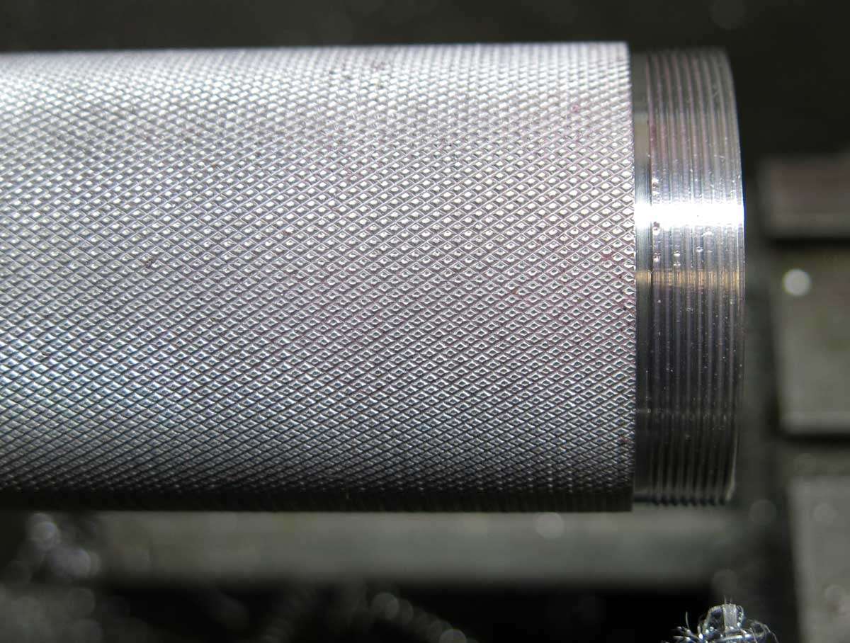
The battery tube was threaded on the head end.
Here are all the machined components sat on top of each other. The tailcap is missing as its not made yet.
The tailcap is shown here being machined from an old off cut.
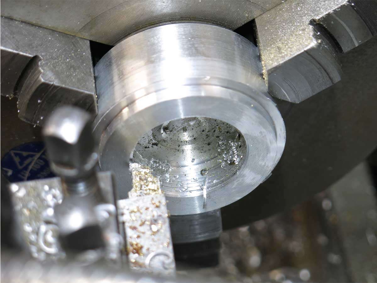
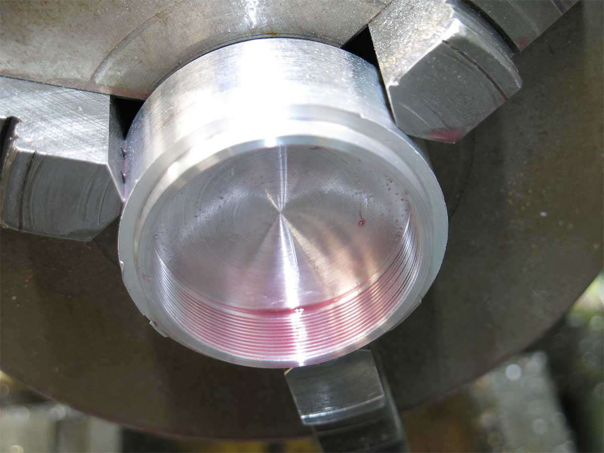
And with the inside after machining had been finished.
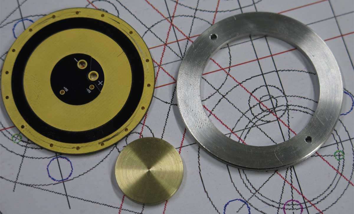
A button was made up to solder onto the plate that will deliver the power to the driver. Its shown here with the threaded retainer.
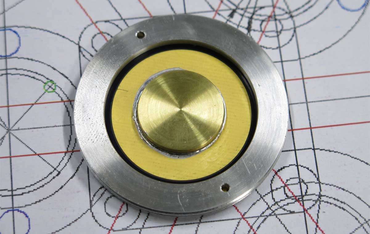
The button here is shown soldered to the adaptor plate, an unused SkyRay king driver. This button was later removed and another soldered on a different thickness after the second lot of mods to the battery tubes.
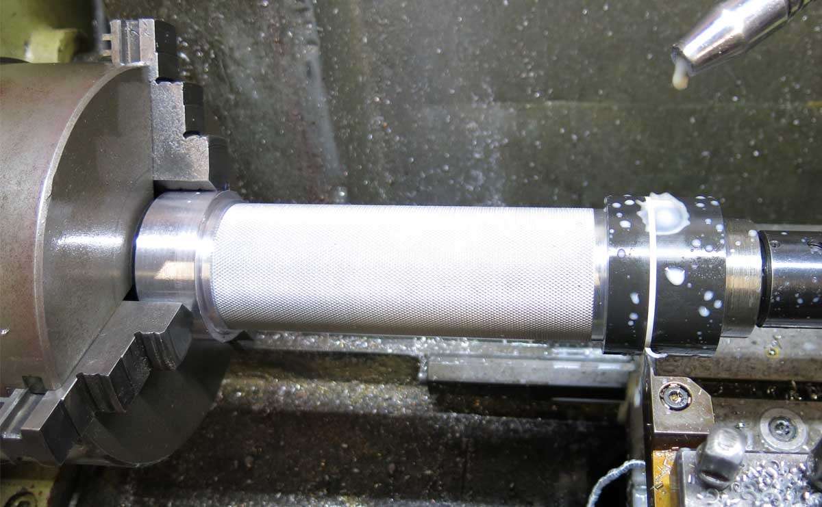
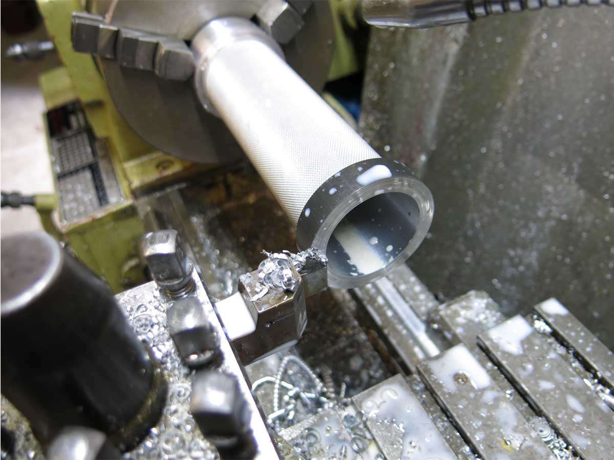
The battery tube was then placed back into the lathe and parted of to length. This was a little nerve racking because if care is not taken a broken parting of tool will result along with a damaged work piece.
The end was then machined down to the correct diameter and threaded to suit the tailcap.
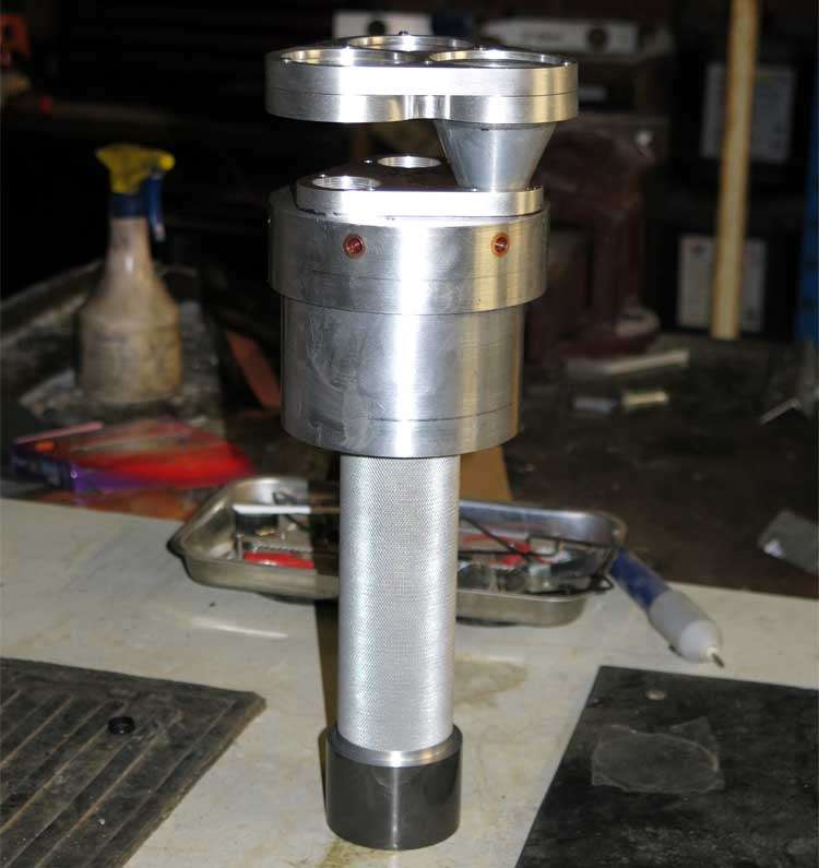
The battery tube with the head and tailcap assembled onto it.
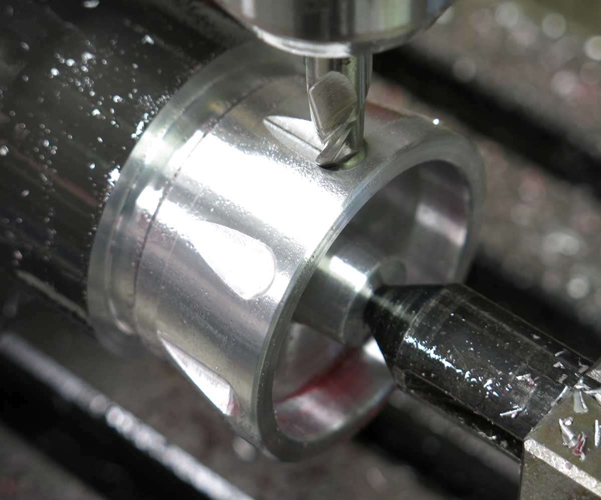
The battery tube in the mill at the start of the machining. Some may not like what I planned for this but it is part of the naked them.
After breakfast I asked the sacked assistants if they would give me a helping hand. Do you think they would even raise an ear? No.

The flats being machined.
Yes, this part had to be re machined again as I did not realise at the time but the tube was rotating backwards and forwards when the 16mm grooves were being machined across the tube.
And finally the see through slots, larger than first planned ![]() , were machined.
, were machined.
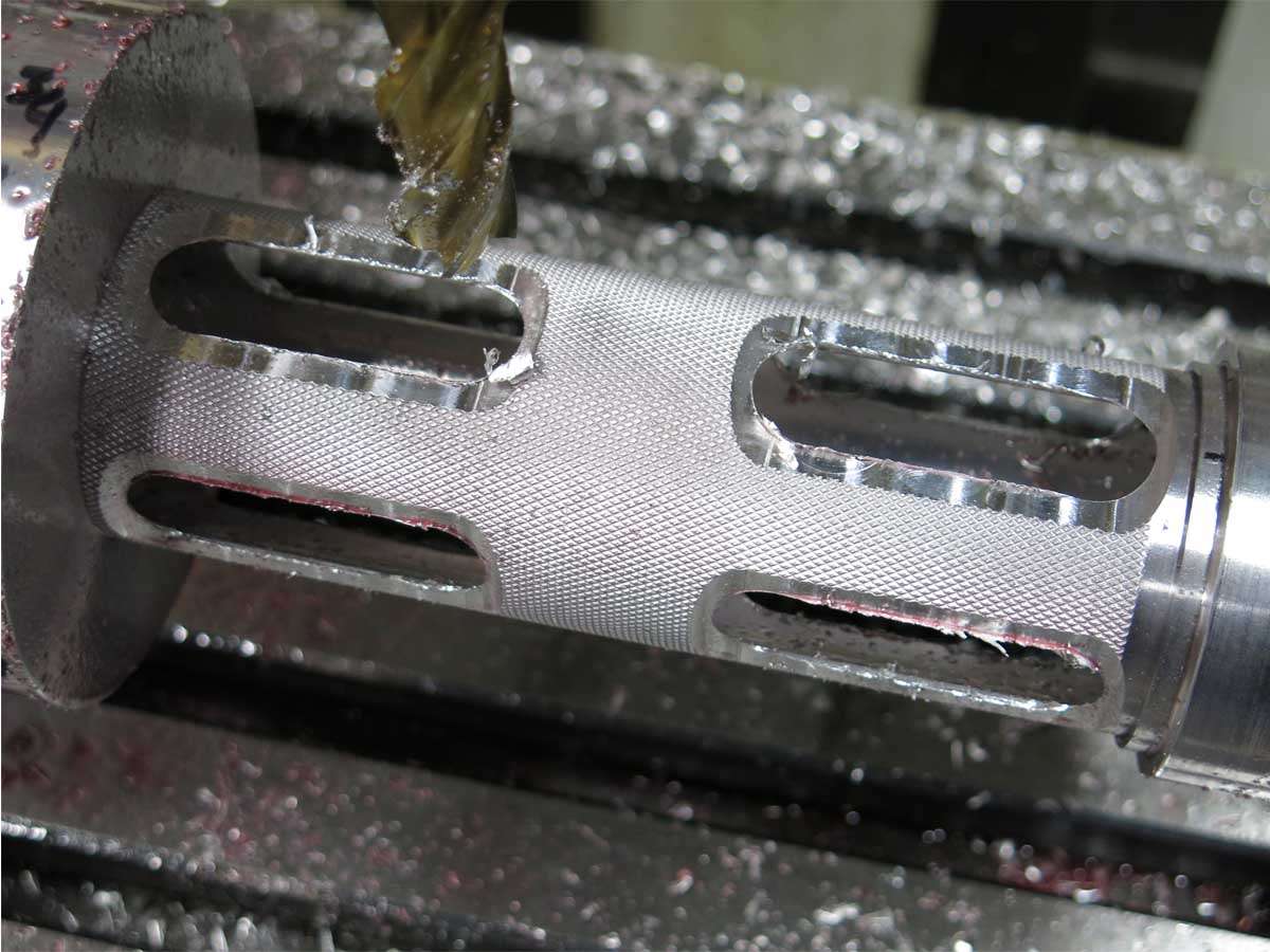
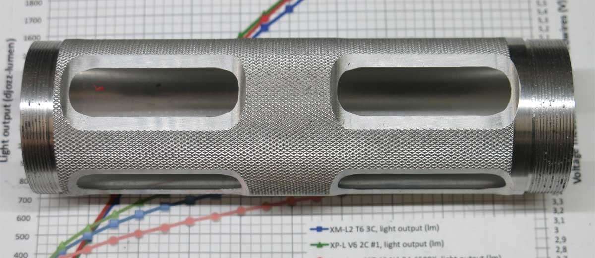
And the see through tube after a little cleaning up with some wet and dry emery paper.
And the final part of this update is the tailcap with the machining nearly finished. The very end is threaded 1/4’’ Whitworth so it may be screwed to a plate and the light used as a lantern when camping.
I’m having a serious case of lathe envy…
Totally off the topic question. You stated ” …drilling the copper heat tubes out from 5.1mm to 6.35mm.” That brings to my mind the question… do you, in modern day metric Australia have an actual 6.35 mm drill bit or is that actually a good old 1/4 inch bit? As someone who ardently wishes the USA switched to metric I am just curious.
And also totally off topic, if you know, what are the common building materials measured in in Australia? For example in the USA a sheet of plywood comes in a 4 foot x 8 foot sheet. It is also sold in Canada, a “metric”country, as a 4 foot x 8 foot sheet. What would the std. plywood sheet size be in the Land of Oz? Thanks, and pardon me for the digression.
Presently it is 60 F, or about 15.5 Celcius outside. Beginning to get somewhat chilly overnight. ![]()
…. and then I see mention of 1/4” Whitworth, which totally confuses me. I haven’t seen Whitworth since the old ’48 Triumph motorcycle I once owned, many many years ago. (I used to ride it in the winter. I would stick a soldering iron in the oil tank to warm the oil before starting the engine. :person_facepalming: Line the front of my pant legs and jacket with newspapers to help keepwarm. ![]()
To try and answer your questions Don.
I own very few metric drills I do have two drill sets starting at 1/16’’ to 1/2’’ with 1/64’’ spacing. Yes you have caught me out. I should of put 13/64’’ to 1/4’‘.
I was in primary school when metric was brought in here but for some reason use both imperial and metric in all sorts of things. :person_facepalming:
I’m not a chippy but a plywood sheet does comes in 2440 x 1220 which is pretty close to 8’ x 4’. My thumb hates bench saws. ![]()
I dont have a 1/4 UNC tap but do have a 1/4 Whitworth. The only difference is 5 degrees in the thread angle and with the tolerance in threads they interchange nicely.
Have you any pictures of the 48 Triumph? You can revive this old thread if you do have any pictures. I love motorbikes but rarely ride these days. My only transport for many years was bikes and yes the cold could be very cold some days and nights. I never had to warm the oil though. :laughing: It was around 1988 when I bought a Dryrider jacket and pants that I found out you dont have to be cold and wet to ride on cold wet days.
lostheplot and I have ridden many miles together. He’s currently riding a Victory and I have a semi retired 850 Yammie in the shed.
Wow - what a weapon!
I thought the tube looked nice like this;
...then I saw the flats after that, where it had cut through, & thought "damn it!"
..then I realized it was the makings of a see-through tube.... which looks great! :D
Those sacked assistants should really be sacked... ;)