Just another data point, but I also always add my bleeder to the spring side of those mtnelec boards. Its just the easiest place to do it.
Both of those things should be done with an iron. The soldering on the spring side of the driver is wide open so there’s plenty of room to work with a fine-tipped iron, which is definitely the easiest way to do that. Plus it lets you “stretch” your solder a bit if you don’t want to fool with scraping off mask.
Replacing the LEDs on the switch board should also be done with a fine-tipped iron, but for a different reason. You really don’t want to point hot air anywhere near that big plastic switch. This kills the switch. Given the choice I use hot air to swap around tiny LEDs and resistors, so having hot air available is really handy, but in this case its the wrong choice. Stick to an iron even though its pretty fiddly and annoying.
Agreed with what emarkd said, but with 1 caveat. Since my driver was soldered to the retaining ring, I needed to use a medium tip with my soldering iron in order to melt the solder. A small tip wouldn’t do it.
I used a precision tweezers to pull the bleeder resistor from the melted solder in the spring area. I stretched the solder as much as possible else if there was too much of a gap I couldn’t stretch the solder on the retaining ring side. There was much trial and error and I went thru a couple resistors since they looked a little burned.
I also use 2 soldering irons to remove LEDs and resistors from the switch board. Put an iron on each side of the component, melt the solder, and like a tweezers, grab the component off the board. And to remove the leftover solder, I melt the solder and quickly swipe it with a toothpick.
Received mine today and just find out that I only purchase the O shaped PCBs (washer?).
Now I need to do another purchase to get the switchboard :person_facepalming:
I tried it but still failed. Here’s what have I done:
1. Soldered 3 SMD LEDs to channel 1.
2. Tested the LEDs, all three can shine together if I direct drive any one of them.
3. Soldered the B pin to bypass because I use no pots.
Now I have difficulties connecting the washer PCB to my switch board (Manker E14), tried several ways but still failed.
Here’s my connection scheme, I hope somebody could help me understand this wiring thing.
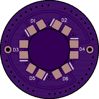
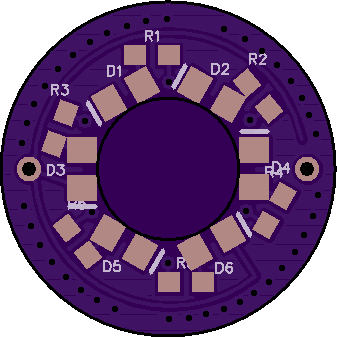
It’s been a little while, but I cooked up another one over the weekend. A Convoy M1 with an XP-L V6 5000K and a nanjg105c driver with Babka firmware. Used a 750 ohm bleeder on the driver. For the tailcap, I used 6 green LEDs on a Rev5.3 board, bridged to a single channel using a 20K ohm resistor. It’s bright. I haven’t measured amp draw, but with a 20K ohm I doubt it’d be much.
Nice work there. I see some blue. Before reading your post, I thought you had a green switch cover with some blue emitters underneath.
Is that OSH board the board that normally has the switch installed on it? I have never looked at those. If it is, you seem to be connecting one switch board to another switch board. Maybe the pic just doesn't show the hole in the center for the switch's button.
I think Wieselflinkpro was saying that you can hook your switch (with it's own PCB as you have pictured) directly to the board that has the emitters and resistors. He called your washer pcb because it looks a little like a washer with a hole in the center.
Please excuse me if I'm totally missing something. I didn't try to dig back into posts to get the back story.
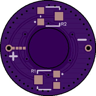
According to the image, I think you have the polarity reversed. With the “HGJ-16” up top, I think the right leg is negative. I always double check myself with a DMM each time just to make sure.
A 1K ohm resistor is probably going to be too little resistance depending on your LEDs and desired brightness. For 6 blue LEDs, I usually use 10K ohm. 20K ohm for 6 green LEDs. Around 6.2K ohm for 6 red. For only 3 LEDs, I’d double the resistance (ie, 20K ohm for 3 blue LEDs).
IRL, it’s pretty green. I don’t notice any blue, but I’m colorblind. Guessing it’s just the color balance of the image. Here’s a pic of a few sitting on my desk. I know these colors are off. From left to right: green+blue, white, blue+white, blue, green. I’m not too good with photo editing to properly adjust the colors.
0.56 mA was too much for me. Sure it looked cool during the day, but it was excessively bright at night. So I tried a 4.64K ohm resistor and measured 0.30 mA. That still was too bright in the middle of the night. I like that the tailcap shines nice and bright since it’s a neat feature, but it also needs to be reasonable. Then I tried a 6.74K ohm resistor and measured 0.20 mA and that seemed about right. Here it is next to the Meteor M43 (on the right) turned on, which was my target brightness.
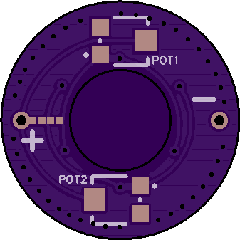
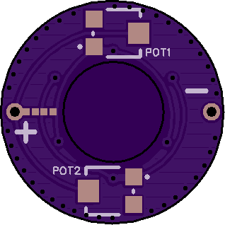
One thing I find a little odd, you have to switch between the 2 potentiometers
Wouldn’t it be better to use those 2 potentiometers to control both LEDs brightness to be able to change the effective light color
and the switch to turn it off and on
for example from Green to yellow-green-yellow-amber-orange red-red
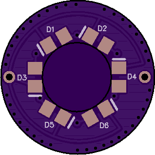
I saw later the 18mm top board but that does not fit a 16mm host, the potentiometers seem to be further out than on the 16mm bottom board
A quick look at a Convoy switch shows me definately polarity reversed
If you got only one sort of LEDs there is no need for a balancing resistor, but thinking of it some balance resistors would be useful to even out small differences of the LEDs like in the first batch of Q8s with uneven LEDs
I liked having a low and high “setting” I could easily toggle by flipping a switch. Being able to vary different colors with the pots sounds cool too. Feel free to continue development in my absence. I make no claims on the designs.