Well, light #3 has arrived this morning and this one is misbehaving. Fortunately I have the two good ones to compare to, and I may have learned something.
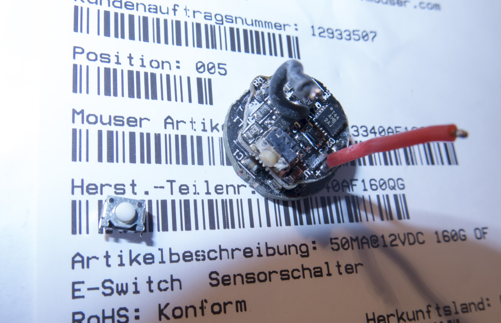
The drivers on these lights have two solder points showing on the battery+ side. On the two good lights, the solder points are precisely horizontally perpendicular compared to the external ‘flat’ on the head housing that the switch is installed in. On the third (misbehaving) light, the solder points are slightly off the perpendicular, being rotated a few degrees clockwise.
Now this third light does work, sort of. I did manage to get it through the programming cycle, and that seems to have remained in the drivers memory - but it’s sometimes reluctant to come on, and reluctant to shut off. Sometimes it gets to ‘low’, one level above moonlight, and then stay there. It’s definitely not working perfectly.
I’m wondering if others might check the alignment of the solder points on their drivers. It could be that the drivers need to be exactly perpendicular to the switch aperture to function properly. Unfortunately I cant seem to rotate the driver - there are no pinholes to twist by, and I can’t tell if it’s glued in or not.