Q8 modding

I am really liking the batch 2's. This is the 3rd one I modded, but for the first two, all I did was the tail mods (bypasses, etc.) and FET replacements. Now that I got in the brass screw replacements for the batch 2's, figured I'd go further with the mod.

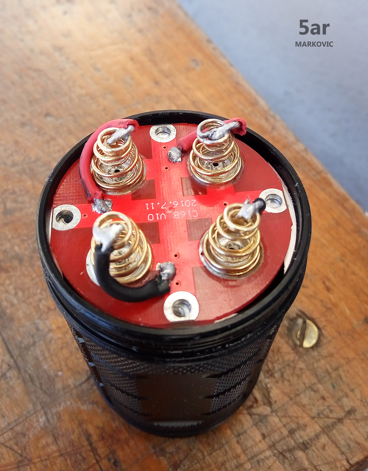
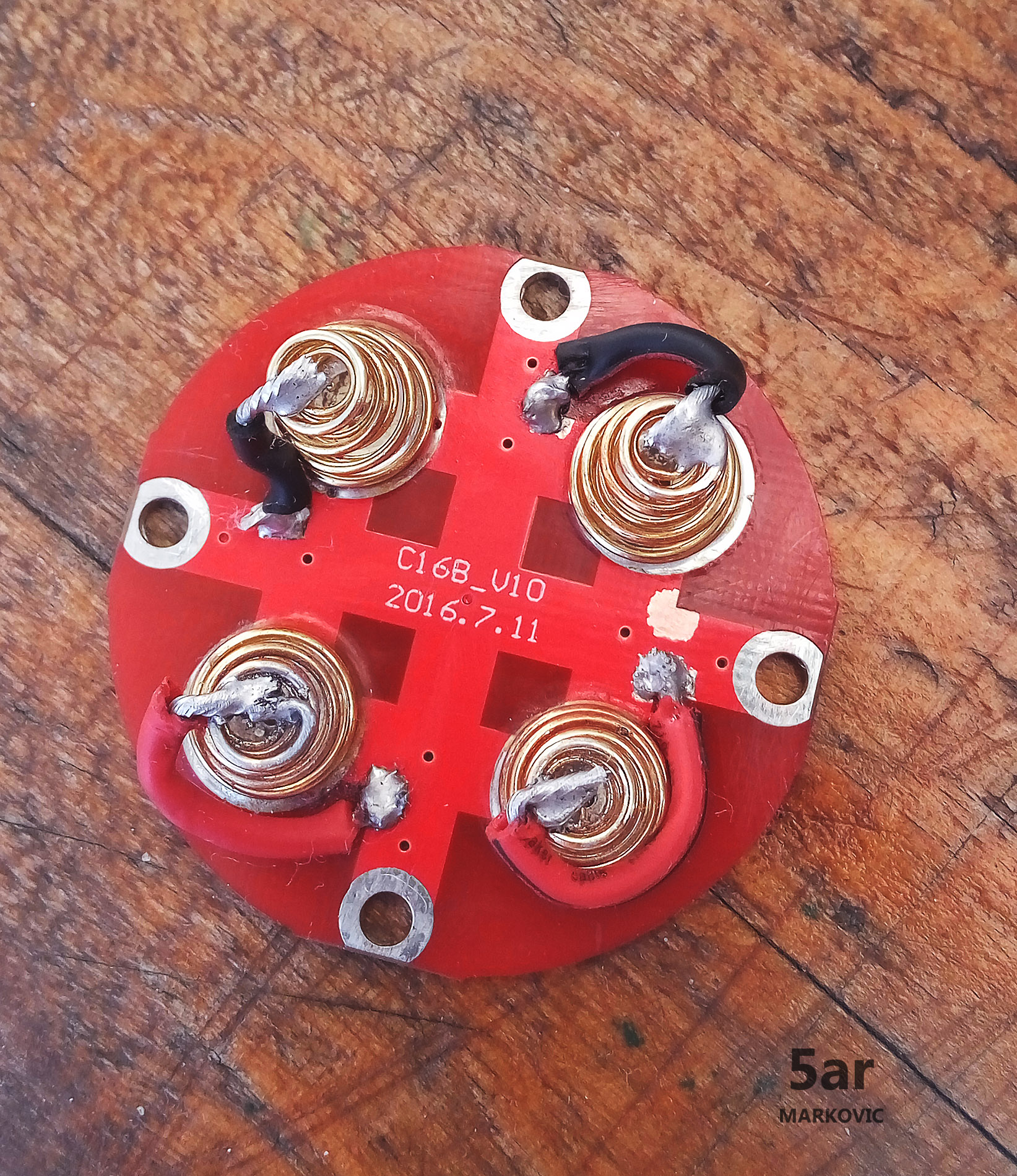
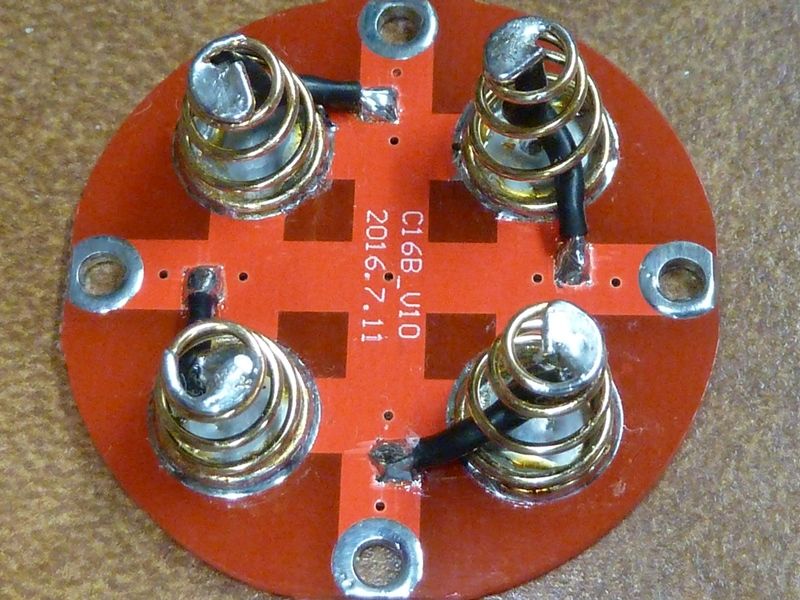
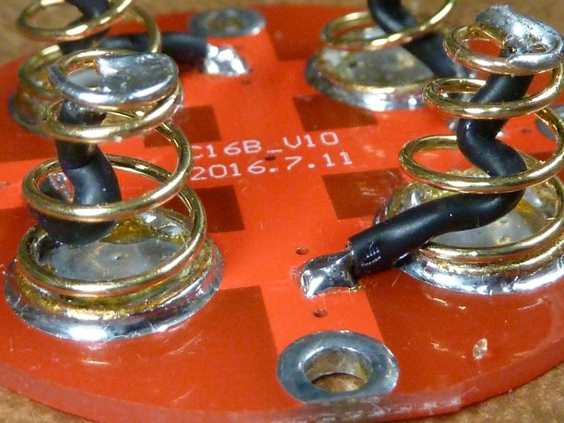
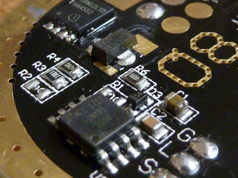
Did my usual 20 AWG bypass method with tossing the inner springs, tinning the rings around the screw holes. See where I'm making the pads on the traces? I'm backing off a little further from the screw hole, hoping the traces will be my acting fuse:

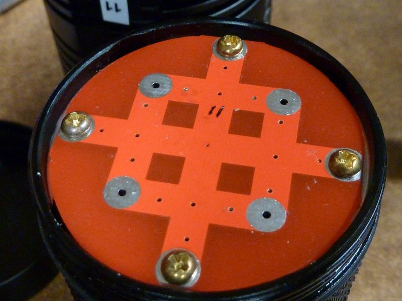
Replacement brass screws M2.5 x 5 mm shown. I'm still sanding down the shelves the screws thread in to, and using light coating of NO-OX-ID:

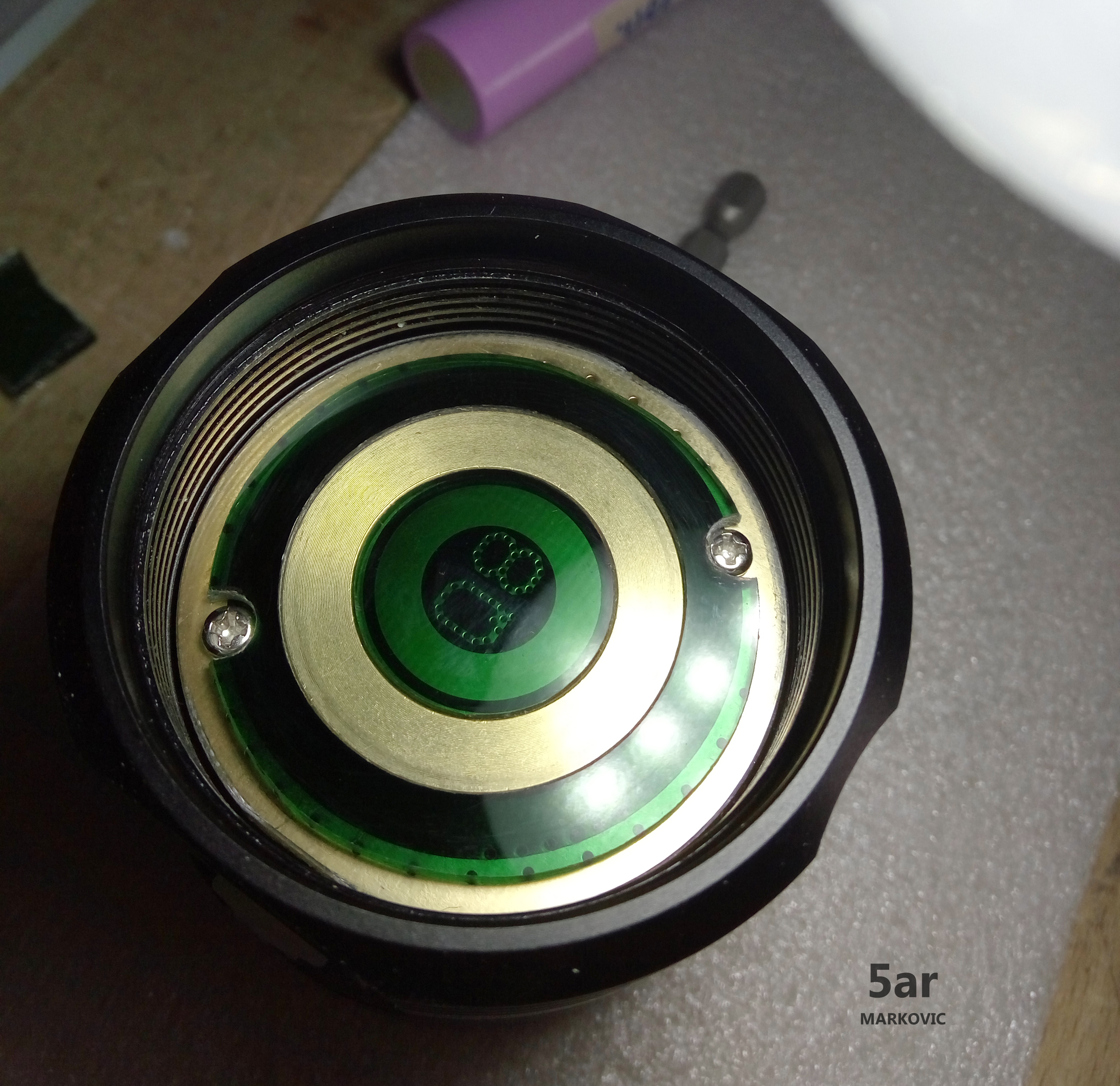
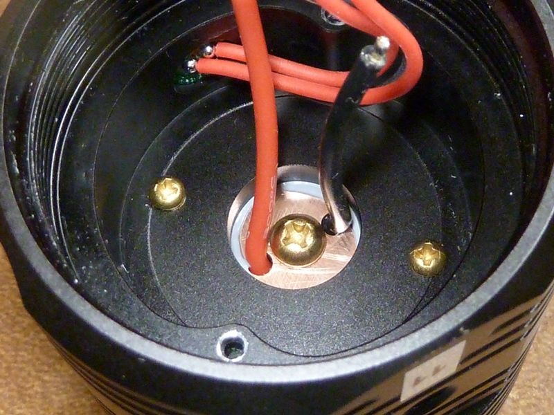
Here's the brass M2.5 x 10mm's and the M4 x 10mm shown. Notice the shiny copper of the MCPCB? It's sanded from 400 to 2000 GRIT, and so is the shelf, then using Arctic MX-4. I got quite a bit squeezed out shown there, more than I thought. I screwed in all 3, but cranked down on the center reflector screw first. The LED's in this light are the best centered I've seen so far in any Q8. I always struggle with batch 1's to get them centered. The stock 18 AWG is replaced with better 18 AWG. The stock ones are stiff, less strands, while the replacement wire I got from IOS a while back: 200C rated and 150 strands. The stock wires in batch 2 are much shorter at 45 mm, batch 1 are 62 mm. I made the replacements 47 mm, but if I were to do it again, I'd use 48 mm. I think 48 mm will be about right for the shortest possible, but still able to get at things easy enough:

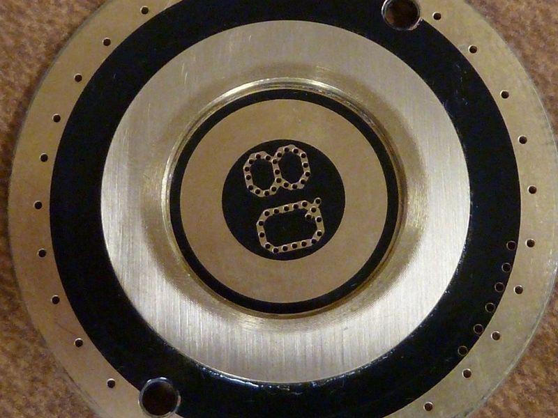
How here's something I haven't see noted yet. The Batt+ contact ring is not flat - it slants down inward. So I got about 2/3's of it level by sadning using 400 GRIT paper initially, then smoothed out to 1000 or 2000 GRIT. You can see below the shiny portion is sanded level:

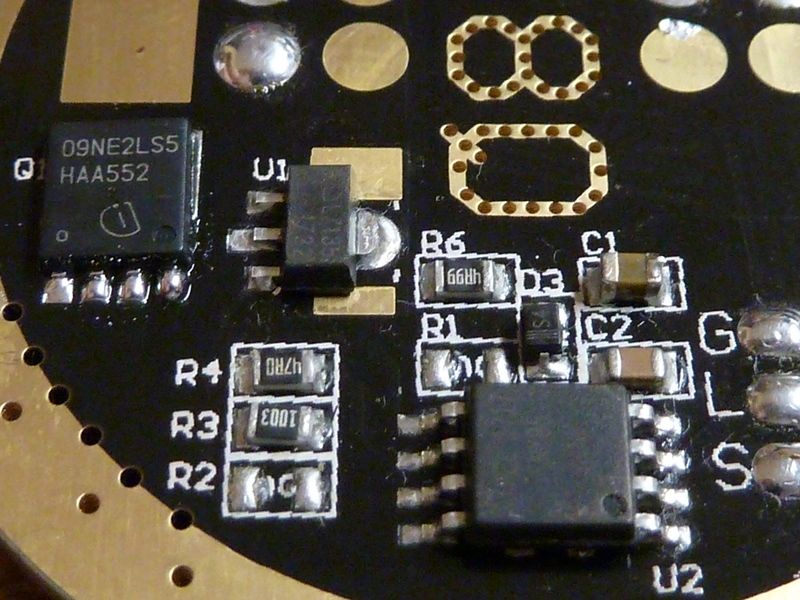
This Q8 got the Infineon FET, shown below. I'm still thinking the SIRA20DP is slightly better, but I got 10 of these to use:

In addition to the above mods:

  • use a bigger drill bit now to bevel the drill holes if not done so already for the critical screw connections
  • stayed with the stock driver screws - no point to replace them
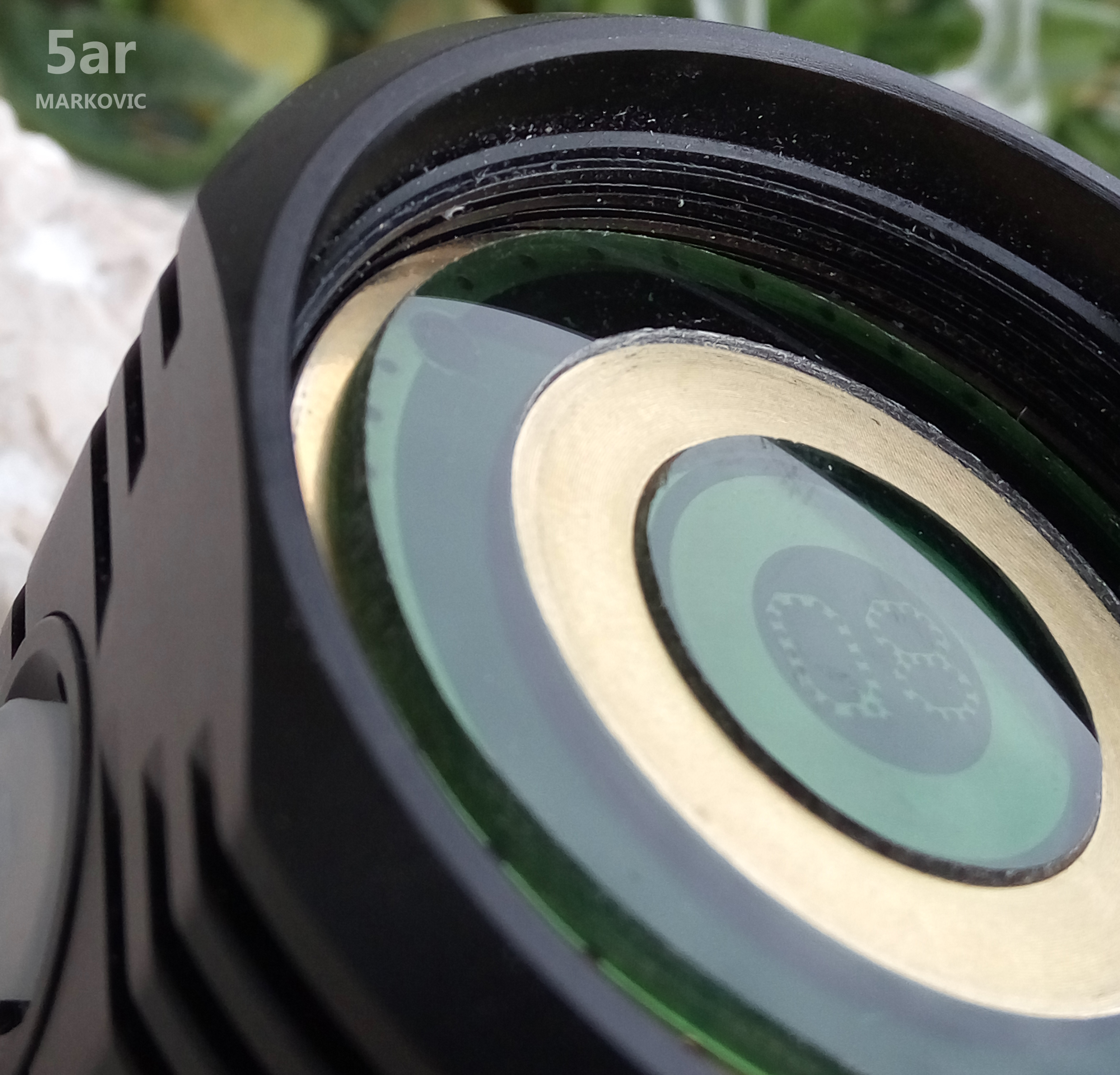
  • this one has regular glass lens, no AR coating
  • sanded smooth the battery tube edge that makes contact to the driver, to 2000 GRIT

So what about the results?

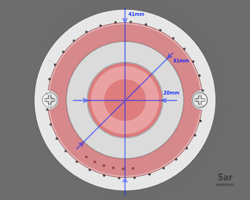
On 30Q BT's @41.9V, lumens: 7510 @start, 6970 @30 secs, 70 kcd taken at 5m (529 meters)

It's the best results I got from a Q8 so far - new record for me.

I made mechanical reverse polarity protection ring. I cut a piece of plastic and thinned to fit. The height of the brass ring is 1.5mm and thickness of plastic is 1.8mm. I did not use any glue, just used a little more pressure to get plastic into the position.

For those who have access to the 3D printer I have made a 3d model.

https://www.thingiverse.com/thing:2625476


I did all this because I wanted bypass spring. Safety in the first place.

[quote=]
I was testing something, put 2 GA cells into a Q8, one upside down, and poof - no light then a small stream of smoke arose... [/quote]

I do not want to see a magic smoke.


Spring bypass 20AWG wires.


I hope this will help you.

the question is who can do this on a lathe

Good Job 5ar!!! :+1: I like it! :beer:

What plastic did you use? Can someone make one for me if you have a 3d printer?

Protection ring or latern extention?

If the price is good, I would buy the protection ring right away…

For lathe I mean a lantern extension, basically a bezel with a bigger base to mount a tube on it with diffusor and cap

The original bezel is fairly slim to mount anything on it with enough mechanical stability

I dont feel this parts usefull…
But my PM is open for any custom drawings.

Nice!
The button top diameter of my older 30Q from Banggood is about 8mm though - so I fear your ring won’t fit all button tops.


You're right. My batteries have a 5mm button top diameter and everything is fit. I did a change for a larger diameter of the top button.


https://www.thingiverse.com/thing:2627854

Thank you. I use colored plexiglass.

I’ve seen a lot of super impressive lumen numbers using fresh cells at turn on and 30 seconds… even from mostly stock lights.

Has anyone measured lumen output with 30Qs once the cells are more depleted… say 3.2ish volts?

Or is there a way to extrapolate lumen output from the data that has already been collected?

Thanks!

Here's some #'s I recorded a few days back:

  • Modded, bypassed Batch 2 light w/stock AR lens on HG2's at 3.56V: 4490 @start, 4320 @30 secs, on full 7135: 180 lumens
  • same modded, bypassed Batch 2 light on HG2 solder tops at 3.35V: 3600 @start, 3300 @ 30 secs
  • same modded, bypassed Batch 2 light on HG2 solder tops at 3.3V: 3440 @start, 3090 @ 30 secs, on full 7135: 180 lumens
  • same light on 30Q BT's @4.20V: 7480 @start, 6870 @30 secs

Well I this afternoon cleaned up properly & modded both my Q8”s.
First I sanded the top of the battery tube where it makes contact with the ground ring.
Then I cleaned & very lightly sanded both the positive & negative contact rings, after ensuring the board was sat flat, & where the screw holes in the tail board contact the battery tube.
I then tinned the screw holes in the tail board where they contact the battery tube.
Lastly I swapped the tail board screws for brass ones.
All this gave me an increase of about 400 lumens from my previous stock reading taking it up to 5860 on start up on freshly charged 30Q BT”s at 4.20v.
I then removed the tail board again, ripped out the small thin inner springs (just pulled them out quite easily) & bypassed the springs with 20awg silicon wire soldered to the board by scraping some of the red coating off halfway between the spring & screw hole.
This resulted in a start up reading of 7650 lumens in my light tube & 6950 at 30 seconds again on 30Q BT”s at 4.20v after 30 seconds.
I am extremely happy with the gains for what are simple, cheap & straightforward mods/cleaning up :+1:

Fun to see the output jump like that after a bit of personal involvement, isn’t it? :smiley:

I’d buy two! I don’t know anyone with a 3D printer, though they seem widely available.

Why buy them? Because I know some day, down the line, somebody is going to get hold of my flashlights and not know what’s not safe to do with them.

Yeah, I know about making things idiot-proof (Nature is always coming up with more clever idiots ….). But I think it’s important to try.

The factory screws sit below the level of the positive contact plate. Nuff said.

Yes it is :slight_smile:
I had previously only seen a big jump like this when I “solder blobbed” the S70 (not that I have done much “modding” previously).
Does this show that the ground path on the Q8 is not very good as stock & in particular the springs are giving a lot of resistance ?
Or does it show that the Q8 is easily modd”able as was one of the design parameters ?
Either way for the extremely low cost of a few cms of silicon wire & 4 brass screws & maybe half an hours cleaning/sanding & soldering the results in terms of lumens gains is fantastic :+1:

Sort of a combination of those things Ian, the springs are typically gold plated steel for mechanical function, so the bypass is always a gain and in the case of 4 cells and 4 emitters it turns into a large gain. Not that factory lights are bad for having springs made of steel but in this case the ease of modification makes it a big plus. Welcome to the world of improved EDC! :slight_smile:

Hi Dale, the Q8 is a bit big for me to personally class it as an EDC light :wink:
Then again as I am on the list for a GT, then in comparison to that monster, I suppose that you could call the Q8 an EDC light :slight_smile: