interested, please add me to list
Please add me to the interested list.
Thanks
Please add me to the list. Thank you!
Please add me as well, thanks!
Looks like this would be useful…please add me to the list for one.
Have tested more of the diffuser designs that I wished to count, (and abandoned all of them) some are ok, but not nearly as beneficial as a down-firing design for lantern use to minimizes eye-glare from the angles that most lanterns will be used. As Miller mentioned it’s a question that been answered many times. One example is i have a head i built to fit on top of a BLF SD-10 ( and other lights with the same sized head) that is very close to your drawing, but like most all types of flashlight diffuser heads of that style, sens eye-stinging glare to the eyes when carried like a lantern by a lanyard, or on a table that is lower than your horizontal plane of view. ( example, when resting on a low table beside chairs at a campsite, or a coffee table, when you look down at it you get the direct view of the LED and its piercing glare. ( which is even worse with the colder tints higher than 3700K.
Bluetooth remotes would just drive the price way to high, and to complex and a feature that many would never use. I have a couple remote control lanterns and the Manker Godmes Bluetooth flashlight. A feature rarely used.
All im looking for in a lantern is:
- 4x18650 or 4x26650 (in parallel). Would be sweet if the battery compartment would be big enough to fit 26650s.
- UBS charging port to charge cell phone etc.
- Modes ranging from 5 lumens to around 500 lumens.
…………Just personal preferences
Please put me down as interested!
Please add me to the list
How did I do that?
I guess by pressing the letter b ?
Im interested in seeing this going to become the first BLF-special lantern. Curious how this is going to look like.
But usually I know that I did what I did. It’s the not knowing that makes me wonder.

What? Why? This is BLF! Let the unnecessary posts stay I say!
I’m interested as well.
Driver progress! We are still in design stage, so a few things will probably change before it is all said and done. But I am close to ordering boards and parts for a prototype.
Basic specifications for the stock setup:
- Constant current drive to LED (no PWM), 0 to 1 A (can be bumped up to about 2 A with a resistor change)
- Output can be adjusted in firmware with 4 mA resolution (255 steps over the 1 A range)
- Firmware is TK’s domain and will probably be a flavor of Anduril
- 2 A charging via a micro USB port. Cells over-voltage protection. Proper charging profile with 128 mA pre-charge, 256 mA charge termination. 4.208 V termination voltage with 0.5% accuracy.
- Power-bank functionality: 2.1 A output for a phone or tablet via a standard USB port
- 90%+ efficiency for charging and power-bank output buck/boost circuits.
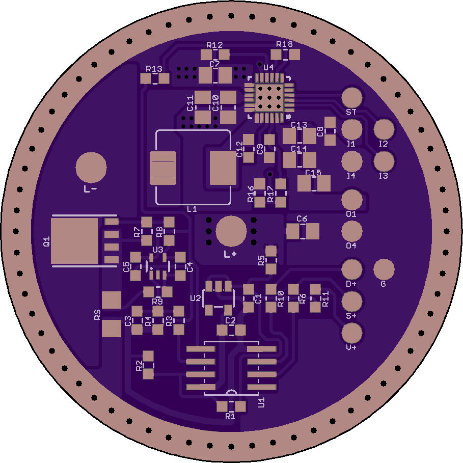
Bottom half is the LED driver, top half the buck charger and 5 V booster.
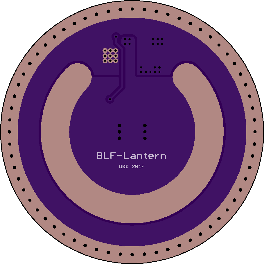
The board is 46 mm diameter ‘SRK’ format. It needs a brass contact ring for the cells+ contact, isolated from the board in the top quadrant. This is an unfortunate necessity due to the power-bank chip’s thermal requirements.
USB ports should be through-hole type for the sake of durability. Not so easy if we want to keep the 46 mm SRK format board. So at the moment they will be on a separate board, together with the diagnostic LED for power bank functionality. The bunch of small wire pads for USB interfacing may eventually get reworked to a small connector.
U3 is a precision DC opamp and does the closed-loop current control for the LED driver (driving a meaty FET in linear mode). A sense resistor creates the feedback signal. The MCU (a venerable tiny85) generates the reference signal. Driver dropout should be < 150 mV, giving regulated control down to about 3.2 V.
U4 is an all-in-one power-bank chip from TI’s BQ24 or BQ25 series (currently looking at the BQ25895, it is also used in the higher end Xiaomi power banks).
Add a second for me, thanks
Nice DEL!
Makes me dizzy to just see the board, and you designed it and actually know why it all is as it is…