Driver progress! We are still in design stage, so a few things will probably change before it is all said and done. But I am close to ordering boards and parts for a prototype.
Basic specifications for the stock setup:
Constant current drive to LED (no PWM), 0 to 1 A (can be bumped up to about 2 A with a resistor change)
Output can be adjusted in firmware with 4 mA resolution (255 steps over the 1 A range)
Firmware is TK’s domain and will probably be a flavor of Anduril
2 A charging via a micro USB port. Cells over-voltage protection. Proper charging profile with 128 mA pre-charge, 256 mA charge termination. 4.208 V termination voltage with 0.5% accuracy.
Power-bank functionality: 2.1 A output for a phone or tablet via a standard USB port
90%+ efficiency for charging and power-bank output buck/boost circuits.
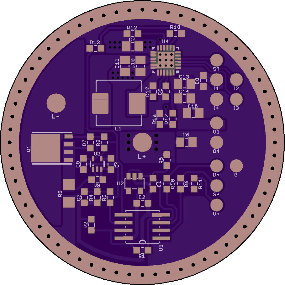
Bottom half is the LED driver, top half the buck charger and 5 V booster.
The board is 46 mm diameter ‘SRK’ format. It needs a brass contact ring for the cells+ contact, isolated from the board in the top quadrant. This is an unfortunate necessity due to the power-bank chip’s thermal requirements.
USB ports should be through-hole type for the sake of durability. Not so easy if we want to keep the 46 mm SRK format board. So at the moment they will be on a separate board, together with the diagnostic LED for power bank functionality. The bunch of small wire pads for USB interfacing may eventually get reworked to a small connector.
U3 is a precision DC opamp and does the closed-loop current control for the LED driver (driving a meaty FET in linear mode). A sense resistor creates the feedback signal. The MCU (a venerable tiny85) generates the reference signal. Driver dropout should be < 150 mV, giving regulated control down to about 3.2 V.
U4 is an all-in-one power-bank chip from TI’s BQ24 or BQ25 series (currently looking at the BQ25895, it is also used in the higher end Xiaomi power banks).
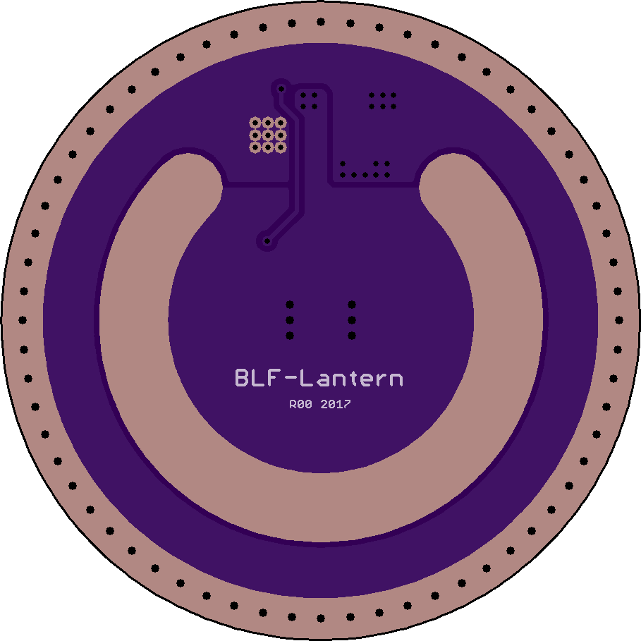
I know it would be bunches more expensive to do, but if a 4-layer board were possible, all the ground planes and thermals could be re-routed away from the ‘center’ ring in the middle layers, leaving us with a ‘standard’ back layer with ‘standard’ v+ and v- rings.
Edit: OSH Park doesn’t support ‘blind’ vias, so that would make re-routing tricky, even with 4-layer boards. But, if we could get it done, I think it would be worth it, even if the cost goes up a bit.
Those are thermal vias, not supposed to be masked. Not sure I would trust just masking either. A short there would be spectacular. The ring would need to be relieved on the back so that it ‘hovers’ in that area. The area should also be sealed up so that a metal shaving or similar cannot get in. Would have been much simpler without the power-bank stuff .
We will have to see what the manufacturer can work with, ditto for the off-board USB ports.
Well, I’m not sure I would trust ‘just’ masking either, but I’d trust it a lot more than ‘not’ masking! If we could get a 4-layer board with blind vias through three layers, but not through the back layer, to spread the heat side-ways to a less dangerous place, that would make me feel better.