Driver progress! We are still in design stage, so a few things will probably change before it is all said and done. But I am close to ordering boards and parts for a prototype.
Basic specifications for the stock setup:
Constant current drive to LED (no PWM), 0 to 1 A (can be bumped up to about 2 A with a resistor change)
Output can be adjusted in firmware with 4 mA resolution (255 steps over the 1 A range)
Firmware is TK’s domain and will probably be a flavor of Anduril
2 A charging via a micro USB port. Cells over-voltage protection. Proper charging profile with 128 mA pre-charge, 256 mA charge termination. 4.208 V termination voltage with 0.5% accuracy.
Power-bank functionality: 2.1 A output for a phone or tablet via a standard USB port
90%+ efficiency for charging and power-bank output buck/boost circuits.
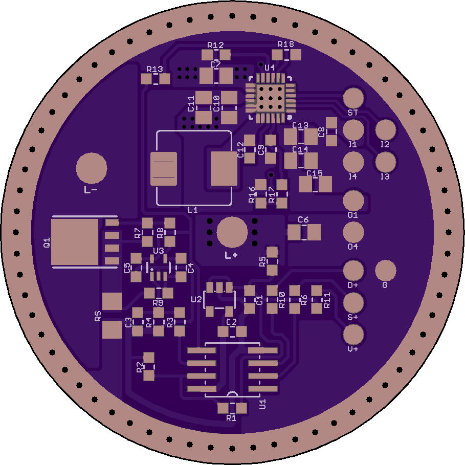
Bottom half is the LED driver, top half the buck charger and 5 V booster.
The board is 46 mm diameter ‘SRK’ format. It needs a brass contact ring for the cells+ contact, isolated from the board in the top quadrant. This is an unfortunate necessity due to the power-bank chip’s thermal requirements.
USB ports should be through-hole type for the sake of durability. Not so easy if we want to keep the 46 mm SRK format board. So at the moment they will be on a separate board, together with the diagnostic LED for power bank functionality. The bunch of small wire pads for USB interfacing may eventually get reworked to a small connector.
U3 is a precision DC opamp and does the closed-loop current control for the LED driver (driving a meaty FET in linear mode). A sense resistor creates the feedback signal. The MCU (a venerable tiny85) generates the reference signal. Driver dropout should be < 150 mV, giving regulated control down to about 3.2 V.
U4 is an all-in-one power-bank chip from TI’s BQ24 or BQ25 series (currently looking at the BQ25895, it is also used in the higher end Xiaomi power banks).
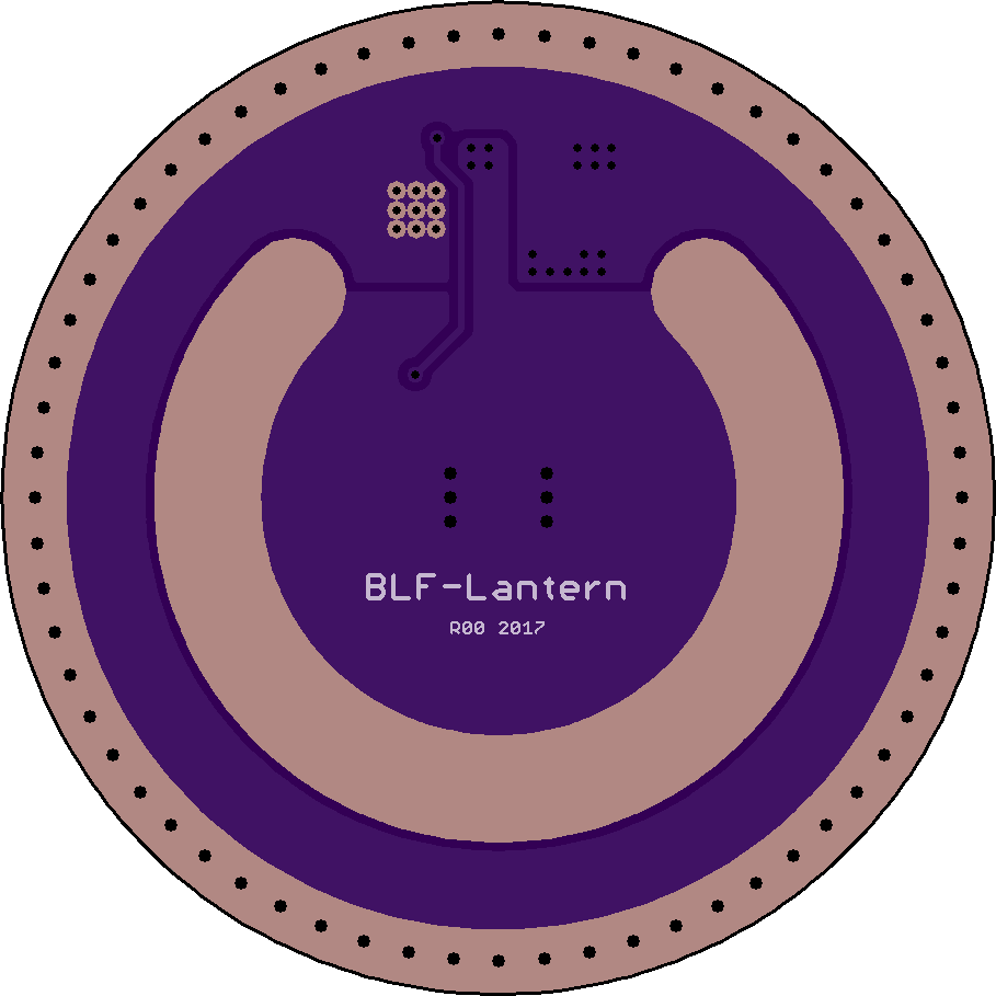
I know it would be bunches more expensive to do, but if a 4-layer board were possible, all the ground planes and thermals could be re-routed away from the ‘center’ ring in the middle layers, leaving us with a ‘standard’ back layer with ‘standard’ v+ and v- rings.
Edit: OSH Park doesn’t support ‘blind’ vias, so that would make re-routing tricky, even with 4-layer boards. But, if we could get it done, I think it would be worth it, even if the cost goes up a bit.
Those are thermal vias, not supposed to be masked. Not sure I would trust just masking either. A short there would be spectacular. The ring would need to be relieved on the back so that it ‘hovers’ in that area. The area should also be sealed up so that a metal shaving or similar cannot get in. Would have been much simpler without the power-bank stuff .
We will have to see what the manufacturer can work with, ditto for the off-board USB ports.
Well, I’m not sure I would trust ‘just’ masking either, but I’d trust it a lot more than ‘not’ masking! If we could get a 4-layer board with blind vias through three layers, but not through the back layer, to spread the heat side-ways to a less dangerous place, that would make me feel better.
What about moving the U4 to be within the inner circle? You’d still have to make a gap in the v+ ring to let the thermal plane thru, but it could be masked and safely bridged across with the brass ring. Is that possible or am I dreaming?
It’ll mostly depend on what DBSAR wants, but for now I’m planning on porting Anduril to it and adjusting the default settings. So you’ll most likely get lightning storm mode, and candle flicker mode, and maybe other stuff. If it has a switch LED it’ll be possible to set the switch LED to high/low/off when the main emitter is off.
This also means you can have a mode group or ramping, and the mode group can be whatever you want… as long as you want 2 or more evenly-spaced levels in sorted order. Want 3 steps? Use 3 steps. Want 18 steps? Use 18 steps. Don’t like moon? Raise the floor. Etc.
Thermal regulation likely won’t even be relevant, so it’s not waiting on me to tweak that for better behavior. Mostly, I’m just waiting for hardware so I can add support for it. It’ll have to use a pin for voltage measurement like on older BLF drivers, and the power control is a little different, and it’ll need ramp adjustments and stuff. But that shouldn’t be hard.
The USB implementation is especially important, everything runs via USB these days, would be great if it could also act as a USB battery bank/5V power source for other devices.
I am very open to having mode “sets” and hidden options that can make the lantern very versatile, and to make it fill as many of BLF members mode likes too. After so much testing with the prototype, ( and all the othr lanterns i modded & built using different drivers and mode firmware, I feel as long as the main default mode is the most used: “Moonlight -Low-Medium-High” set, and other sets can be including a ramping set, and sets including the lightening effect mode, and a candle flicker mode.
Maybe something like this below:
Mode set #1 Moon, Low, Med, High (DEFAULT)
Mode set #2 Moon, Ramping from 5% to 100%
Mode set #3 Low, High, strobe, SOS, 2second-Beacon, 4second “lighthouse” (meaning 4-seconds off, 1 second on for marine/ onboard boat safety beacon use)
Mode set #4 Moonlight, Low, Candle flicker, Lightening-effect, etc.
And if its not to difficult or complex a battery-voltage check hidden mode option?
Having a USB charging and charger output option on this lantern would definitely be a real great benefit for off grid & camping use, especially if high-capacity cells are used, (3500mah or higher X-4 ) it would be a powerful powerbank & a long run time lantern. The ability to charge a phone & run a lantern and even be charged via solar charger at the same time would make it the perfect long term off grid or long duration expedition valuable tool.
Well, battcheck is “hidden” on 3-clicks-from-off, if that counts. The blinkies aren’t part of any mode groups; they’re off in their own separate part of the UI. Specifically, it has two blinky groups tied to triple-click:
Click 3 times from “off”: Battcheck, sunset mode, adjustable-speed beacon, tempcheck.
Click 3 times from “off” but hold the third click: Biking, tactical strobe, motion-freezing strobe, lightning storm, candle flicker. Remembers which one was used last. Everything except lightning is adjustable.
Instead of a 2-second and 4-second beacon, it has an adjustable-speed beacon where you tell it how many seconds each cycle should take.
SOS doesn’t exist but is easy to add… if anyone cares. The most interest I’ve seen in it is speculation that someone somewhere might care.
Everything related to 1 or 2 clicks is a shortcut to regular output modes. 3 clicks for blinkies, 4 clicks for lockout, 5 clicks for momentary, 6 clicks for muggle mode.
There are basically two regular-output UIs — smooth ramping or a mode group. They use the same actions for the same purposes, but one is smooth while the other has a specfic number of discrete levels. Those actions are:
From off:
1 click: Turn on at memorized level.
Hold: Turn on at lowest level. Keep holding to get brighter.
2 clicks: Turn on at ceiling level. Repeat to go to full turbo, if it’s higher than the ceiling. Once at full turbo, repeat to go back to memorized level.
2 clicks, but hold second click: Turn on at ceiling, then keep holding to get dimmer.
While on:
1 click: Off.
Hold: Increase brightness. Release and hold again to decrease.
2 clicks: Toggle between turbo and memorized level.
2 clicks, but hold second click: Decrease brightness.
3 clicks: Toggle between smooth ramping and mode group.
4 clicks: Configure current mode — floor, ceiling, and (if relevant) number of steps.
The default can be moon/low/med/high, and regular use can be explained in just 8 words: Click for on/off, hold to change brightness.