I received today a Emisar D4 to change its XPG2 S4-5D LEDs with Nichia sw405 D240 CRI92 and spring bypass it

So I can take a look inside it
finished light
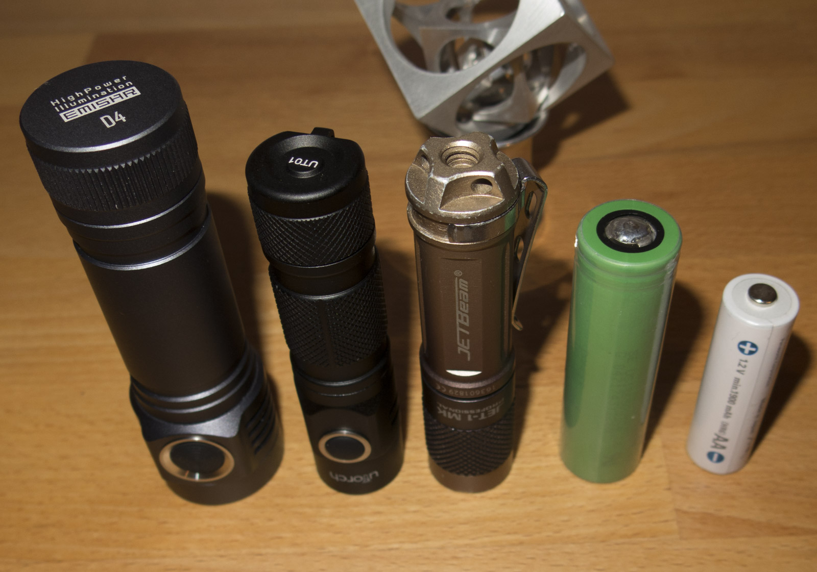
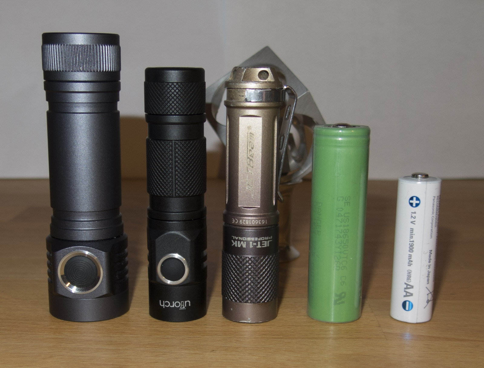
Size comparism
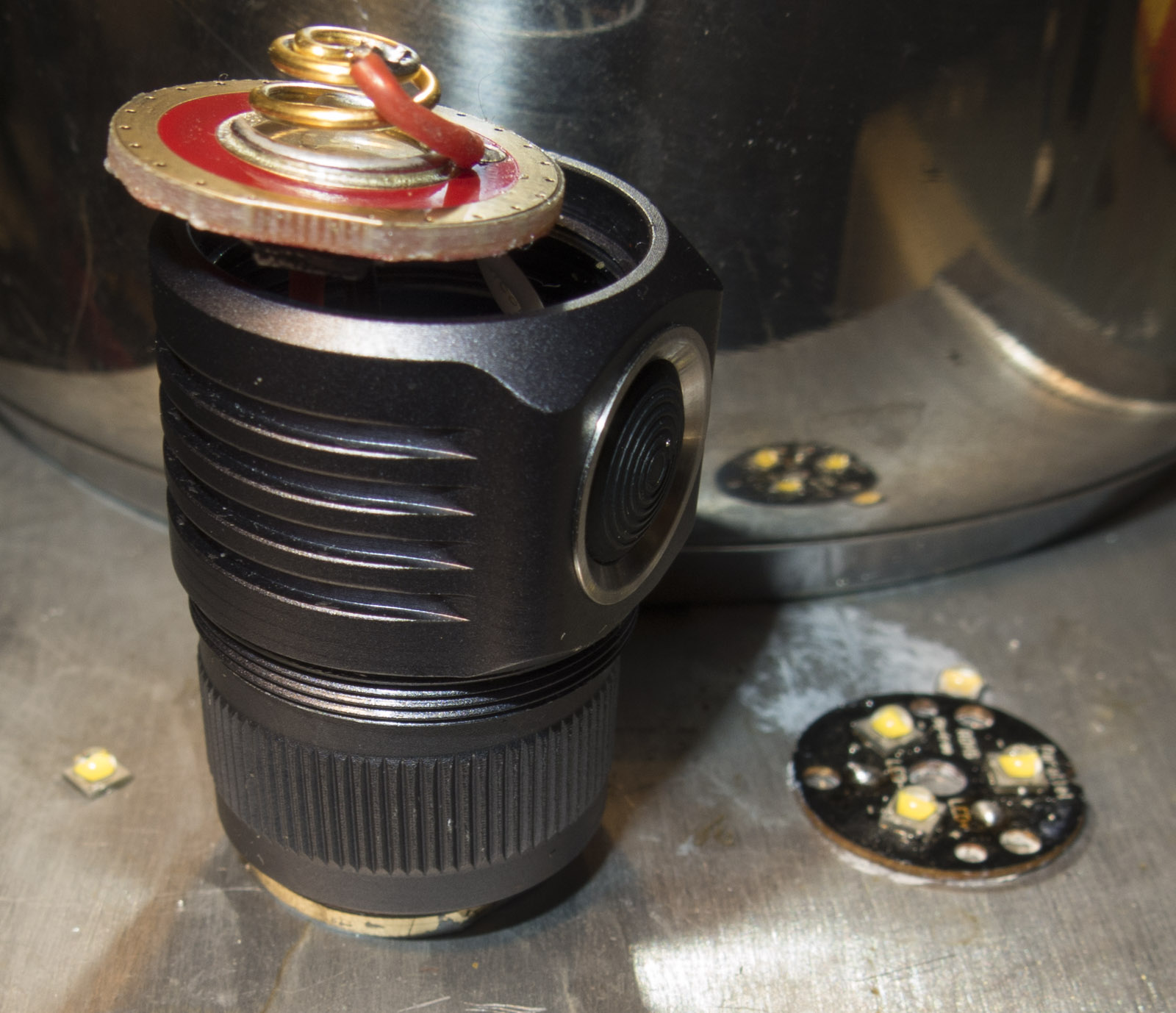
Spring bypass

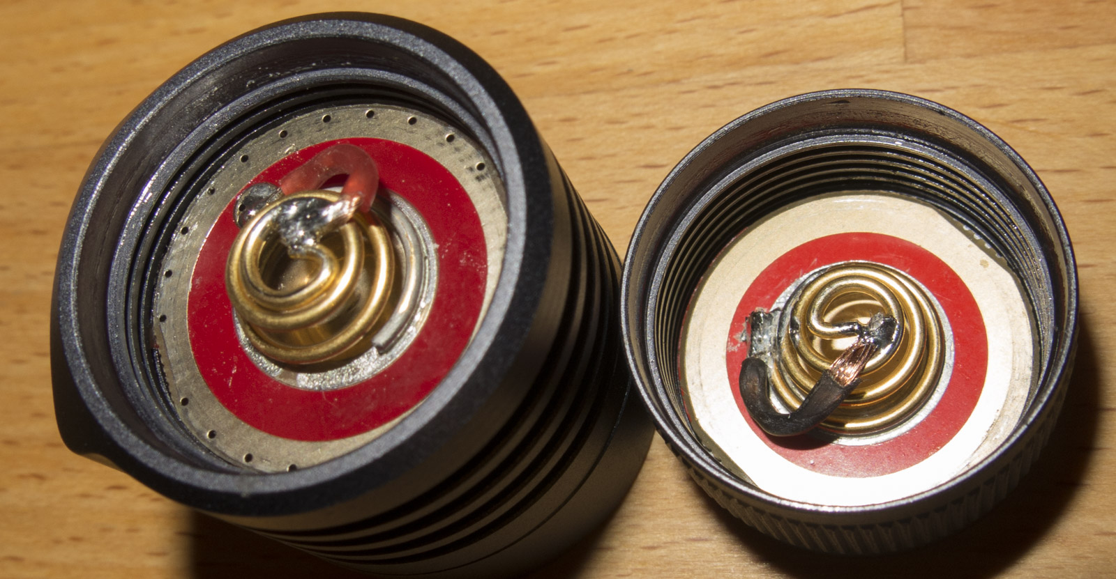
I also noticed there is very little solder paste on the springs but they seem to hold fine
Threads are cut square very nicely

The light is build like a Tank shelf and all walls are very thick even the tube

The driver is so designed that the MCU and AMC have contact with the shelf, so temperature reading of the MCU should be pretty precise, I do the same on my Klarus XT11GT Repairs with Narsil driver
It uses a Infineon Power-MOSFET, BSC009NE2LS5 in PG-TDSON-8 (also know as Power SO8 or LFPAK56)
This FET looks pretty good from datasheet comparable with beating the Vishay ones in low Resistance 1.2mOhms @3,5V
I wish the side switch would have LEDs like my Q8

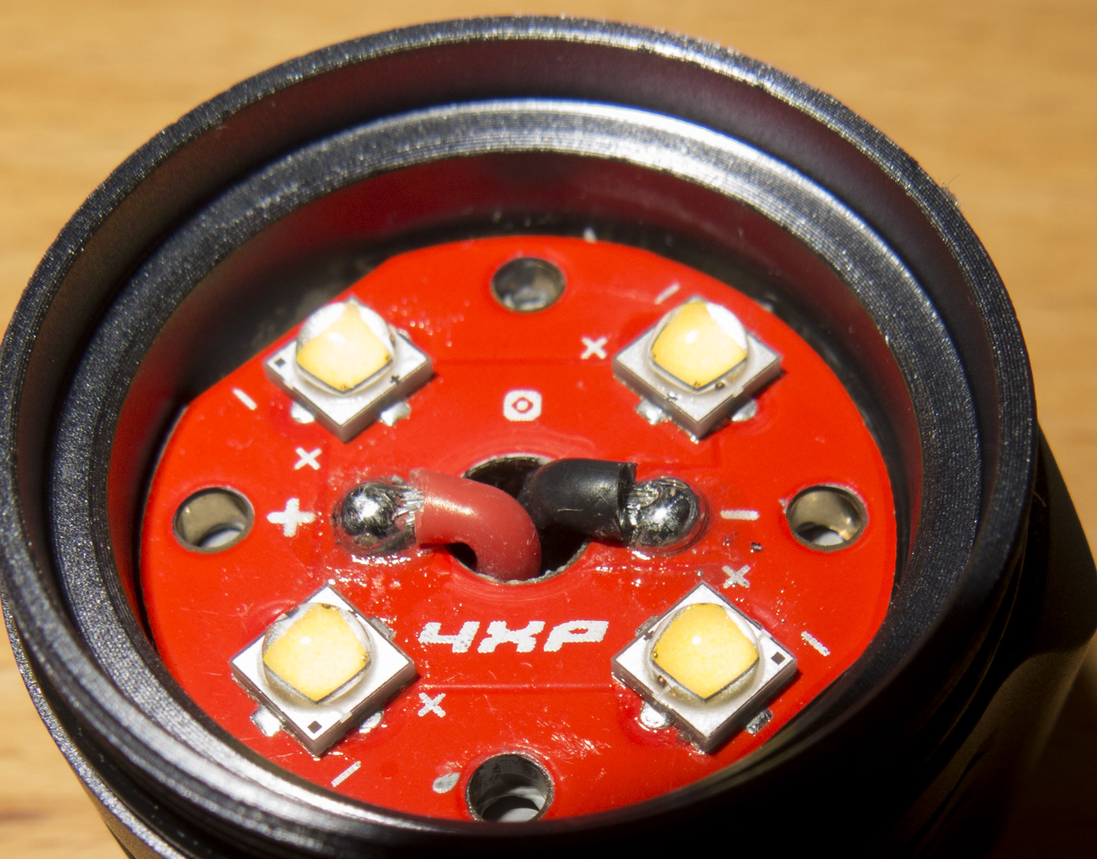
The LEDs are reflowed with very much paste, it would be better to give em a tap to push solder out to get it as thin as possible or use less
the LEDs are reflowed with Leaded solder
Reflowed Nichia SW405 D2450 CRI9050 in it

Used my temperature regulated heat plate
Gave the LEDs a tap to remove too much solder, so also a lot solder blobs are all over the place
carefully aligned the LEDs to the markings if they were off
Used a little weight to push the LEDs down while cooling the heat plate with water filled pot
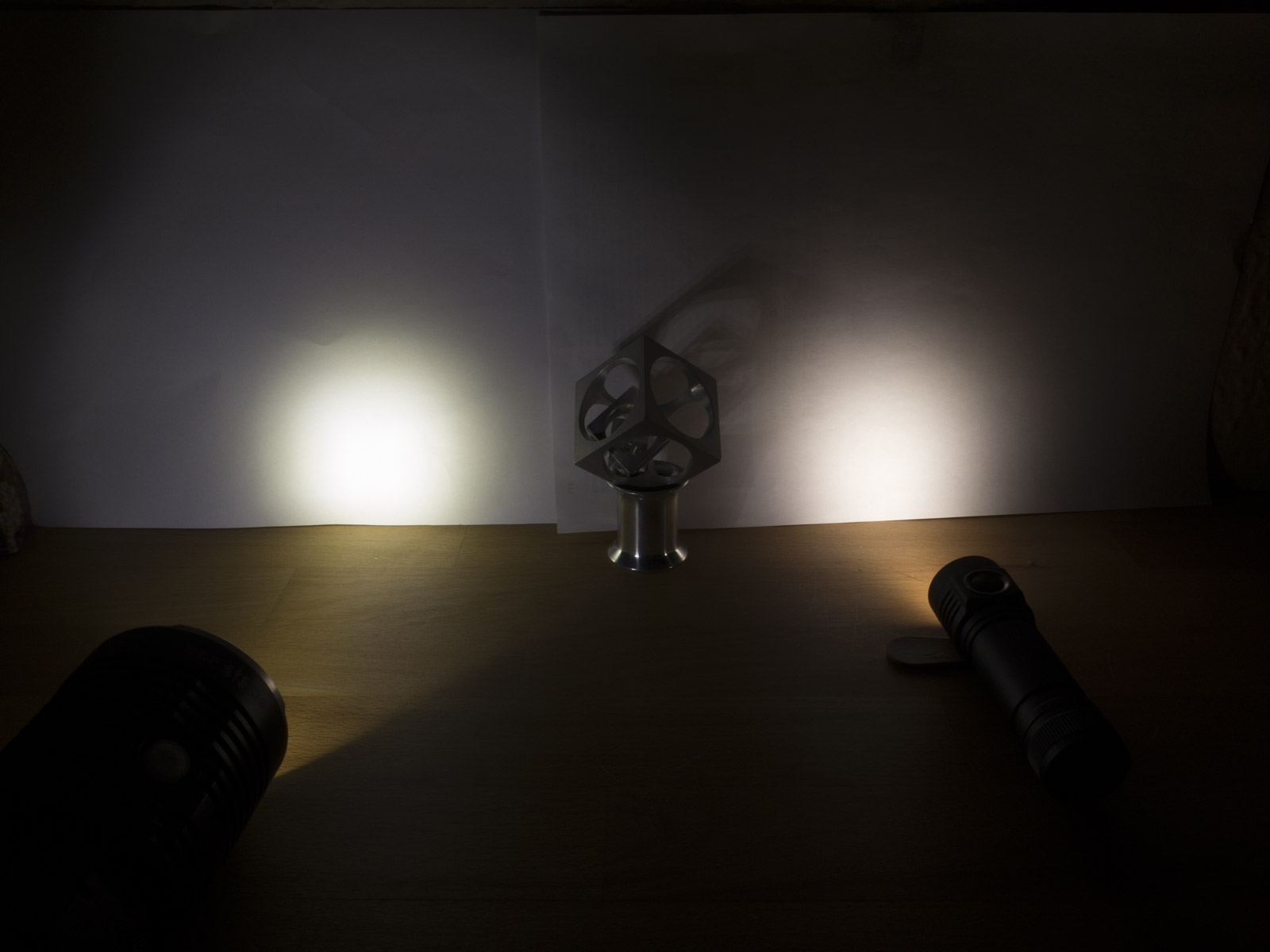
Light is now drawing 15.8A at 4.1V Sony VTC6 battery
Compare to the BLF Q8 with one battery with same charge level and type as in the D4
I also looked at intl outdoor website again and noticed the XPL Hi are now +18$
Conclusion:
Overall well build light and UI.
Great optics and MCPCB.
Pretty short for a 18650 light, possible EDC in pockets.
The only downside in my opinion is that the switch is not lighted.
