Tailcop mod cant work without a bleeder from batt+ to flaslight body
I have a bleeder resistor (750), and on the board it has 3x123 resistors,
im building another driver and was wondering does anyone have a picture like on post #1635 but on the purple MTN-17DD board ? where i could cut a trace or another location for the bleeder
Got a link to which driver you’re talking about? I don’t know (/can’t tell) what the purple driver is. Essentially, with any driver you’re looking for a convenient place to bridge + and - with a resistor.
just like this but does not have the zener pads
http://www.mtnelectronics.com/index.php?route=product/product&path=25_122&product_id=272
According to the image, the spring side has the same solder mask layout. Bleeder could be placed in the same position as pictured in post #1635.
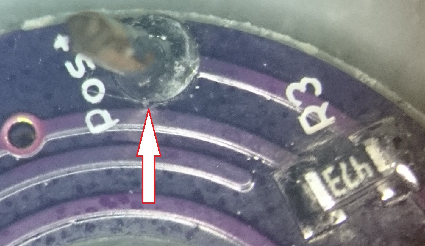
Well, I just encountered my first problematic boards from OSH Park. I ordered 9 of Rev 5.3 Top boards (of which this is probably my 3rd or 4th order) and 3 of them have channel 1 and 2 accidentally bridged. I tracked it down to here:
It looks the trace around the through-hole encroached onto the trace sneaking just outside of it. Of course I found this after reflowing all of the LEDs (of two colors) onto the board. Luckily I was able to carefully score the trace and separate the channels. The remaining two boards have been tagged and I’ll just use them for single-color tailcaps.
That said… I’m sure this is pretty isolated, but could the design be tweaked slightly to try and avoid this? It looks like a couple of those through-holes are pretty close to other traces. (as I write this, I see that PD has been gone for almost 2 weeks… I hope all is well!)
PD is a less frequent visitor nowadays. But thusfar he has been around every now and then ![]()
I gave up on mine lol i cant get it to work, i used a FET driver and used a 750ohm resistor on the driver like the picture above and the resistors that is on the bottom and still nothing, switch works,leds work, driver and light works ? i give u guys credit for who got yours working
Its most likely a polarity issue. Either your ring board is wired backwards to the switch or your little LEDs are sitting backwards on their pads. Did you test the ring board outside of the light? Like this…

…or mounted to the switch, like this…

Just make sure the switch is “off” (open) before doing this or you’ll be creating a helluva short across either your cell or your power supply.
Yes emarkd mine looks just like that, i put my test leads to the bottom spring and click the switch and they come on and off, But once its in the tail cap and all hooked up they do not power on and my driver does some weird mode changes and dims the led ?
im using a one 751 resistor on the driver from ground to the spring and 3 resistors on the bottom (123)
so i tried it again and again everything tested out to be working when i turn the switch on and off, installed it into the light and it comes on automatically and when i click the switch it gets brighter and click off it goes lower but stays on ?
I hope you can figure this out Lights-Out. I’d suggest using a lower bleeder resistor value (I had to go as low as 220 ohms to get mine to work), but it seems something else is causing your problem.
BTW, I see that the Convoy store now stocks the lighted switch pack mentioned above in post #1619: lighted switch for convoy flashlight.

You sure its not shorting to the body of the light somehow? There’s solder joints on the top of the ring board that could be touching inside the tailcap, plus if you’re wiring yours like mine - soldering to the switch tabs - it would be easy to get a bit sloppy with that and have them extend outside the confines of the board itself, where they could maybe touch the sides of the light. I’d try insulating everything, wrap it all in kapton or something, and see if that fixes it.
i got it to work but it is loosing connection at the spring so im guessing the switch board is bad ? anyone know where i can order a few i think its 20mm
I forgot, which light is this going into? I always struggled with grounding at the tailcaps on my Convoy S2’s. The setup makes the switch retaining ring sit too low and there battery tube won’t make good contact. I usually end up building up the switch board thickness with some solder on the grounding ring. Not a good long term solution but it works.
It’s a rigid industry flashlight and looks like the older C8’s
I found mine. It was an earlier version.
Gotcha. I thought I remembered someone else running into a similar problem before. Man, what a bugger to pin down!
This is my first post here, so I welcome everyone. My name is Adrian.
I’d like to add this switch to my s2 +. I added a bleeder to the driver, but it still does not work as it should. After switching off and on again, the mode changes to the next one. I’ve tried a bleeder 10k, 4k7, 1k, 750R, 680R, 470R, 240R and even 68R, but it still does not work. I am a beginner, so please be understanding and make suggestions.

What color leds do you using and what resistor values did you placed in the tailcap before them?