You sure its not shorting to the body of the light somehow? There’s solder joints on the top of the ring board that could be touching inside the tailcap, plus if you’re wiring yours like mine - soldering to the switch tabs - it would be easy to get a bit sloppy with that and have them extend outside the confines of the board itself, where they could maybe touch the sides of the light. I’d try insulating everything, wrap it all in kapton or something, and see if that fixes it.
i got it to work but it is loosing connection at the spring so im guessing the switch board is bad ? anyone know where i can order a few i think its 20mm
I forgot, which light is this going into? I always struggled with grounding at the tailcaps on my Convoy S2’s. The setup makes the switch retaining ring sit too low and there battery tube won’t make good contact. I usually end up building up the switch board thickness with some solder on the grounding ring. Not a good long term solution but it works.
It’s a rigid industry flashlight and looks like the older C8’s
I found mine. It was an earlier version.
Gotcha. I thought I remembered someone else running into a similar problem before. Man, what a bugger to pin down!
This is my first post here, so I welcome everyone. My name is Adrian.
I’d like to add this switch to my s2 +. I added a bleeder to the driver, but it still does not work as it should. After switching off and on again, the mode changes to the next one. I’ve tried a bleeder 10k, 4k7, 1k, 750R, 680R, 470R, 240R and even 68R, but it still does not work. I am a beginner, so please be understanding and make suggestions.

What color leds do you using and what resistor values did you placed in the tailcap before them?
You need to wait about 5 seconds before turn off to memorize the last mode
Welcome to BLF Leviatan!
When contact is broken upon a switch (half)press, normally the driver measures the time before contact is resumed, if that is quick enough it interprets it as a switch to the next mode, if it is longer it interprets it as a switch-off. That timing is often influenced by the lighted switch assembly, and can be so off that even a long switch-off is still seen as a mode-change.
I have had drivers that I never got to work with lighted switches, I remember having trouble with 105C-type of drivers, but can’t remember how bad it was.
Being somewhat of a noob myself, is connecting the bleeder resistor between the spring (battery plus) and the star the same as connecting it to the ground (the flashlight body)? I thought the stars are used to change driver functions and perhaps that’s not connecting it to ground.
Leviatan, have to tried soldering the resistor between the spring and the outer ring (or you could solder it to the middle pin of 1 of those 7135s)?
Star #1 is directly connected to the grounding ring, it actually can’t be used for changing settings (whereas stars 2, 3, & 4 can be in your typical star firmware). That placement is exactly how I do all my 105c drivers.
This is the reason why drivers like Bistro HD OTSM were developed, the bleeder does not mess up the off timing as the MCU is powered on while the switch is half pressed
OTSM driver can be used with MOSFET or without, depending which mode group you use, but strobes use the FET
So if you use it with FET upgrading to a DTP LED board is nessesary if you put high drain cells in the light
There are two blue leds. 360R for each.
I can wait even 2 hours, but still mode is changed.
I never tried with such a low value in tailcap, the lowest was 2k
Did you test without the bleeder resistor?
I use normally 15K to 30K in the tailcap and 470R bleeder
Normal behavior of the memory of the 105
Turn on> wait over 5 seconds -> turn off -> turn on last mode
Turn on> wait less 5 seconds -> turn off -> turn on next mode
Or
Turn on> wait over 5 seconds -> tap (medium press) -> no change mode
Turn on> wait less 5 seconds -> tap (medium press) -> change mode

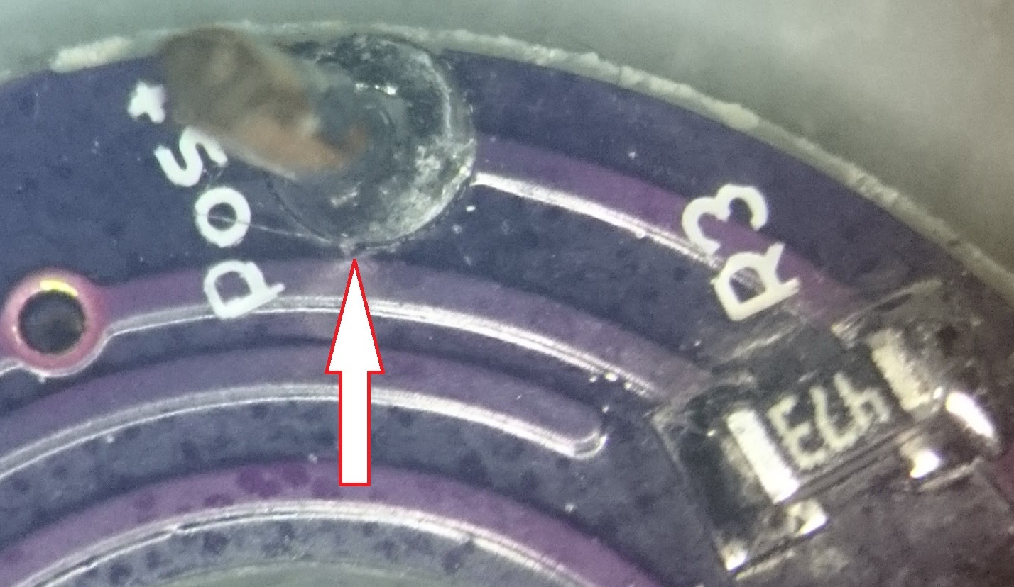
What is this?
These components do not remember that they are in my 105


These resistors (360R) were original there. Without bleeder, the modes do not change.
This driver doesn’t have a default firmware. It is a driver with proprietary software, and is specially modified for this.
I will try to replace the resistors.
I replaced the resistors. As a bleeder, I gave 240R, and for LED 4k7. I also tried 2k2 for led and it did not work. It works, but it is not bright…
I use 560 Ohm or 1K as bleeder and 4,7K to 47K at tailcap depends on what brightness I want. Blue leds are fine with 1K bleeder and 10 to 47K at tailcap.
With 2.2K and a transparent washer and tail boot it should be quite bright
The best way to get really bright tailcap is getting the washer replaced with a board so the LEDs are very close to switch cover
Lighted tail switch board replacing the washer around the switch
16mm
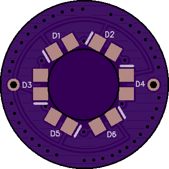

17mm
https://oshpark.com/shared_projects/yplKNhqL
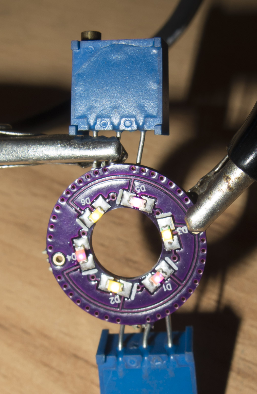
Tail board without balance resistors tested successfully
Pink and warm white in the 2 I tested
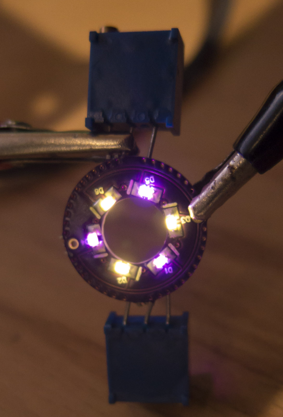
3x3mm Potentiometers will take a while from China
Have such boards ready but not yet the potentiometers
If you want very bright tail caps you have to go to Bistro HD OTSM drivers