
What is this?
These components do not remember that they are in my 105


What is this?
These components do not remember that they are in my 105
These resistors (360R) were original there. Without bleeder, the modes do not change.
This driver doesn’t have a default firmware. It is a driver with proprietary software, and is specially modified for this.
I will try to replace the resistors.
I replaced the resistors. As a bleeder, I gave 240R, and for LED 4k7. I also tried 2k2 for led and it did not work. It works, but it is not bright…
I use 560 Ohm or 1K as bleeder and 4,7K to 47K at tailcap depends on what brightness I want. Blue leds are fine with 1K bleeder and 10 to 47K at tailcap.
With 2.2K and a transparent washer and tail boot it should be quite bright
The best way to get really bright tailcap is getting the washer replaced with a board so the LEDs are very close to switch cover
Lighted tail switch board replacing the washer around the switch
16mm
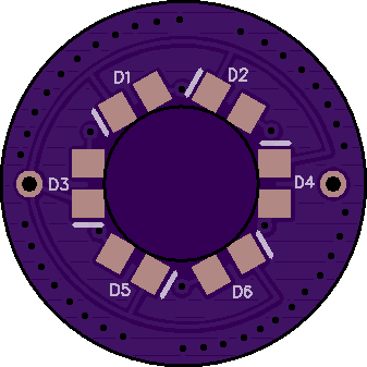

17mm
https://oshpark.com/shared_projects/yplKNhqL
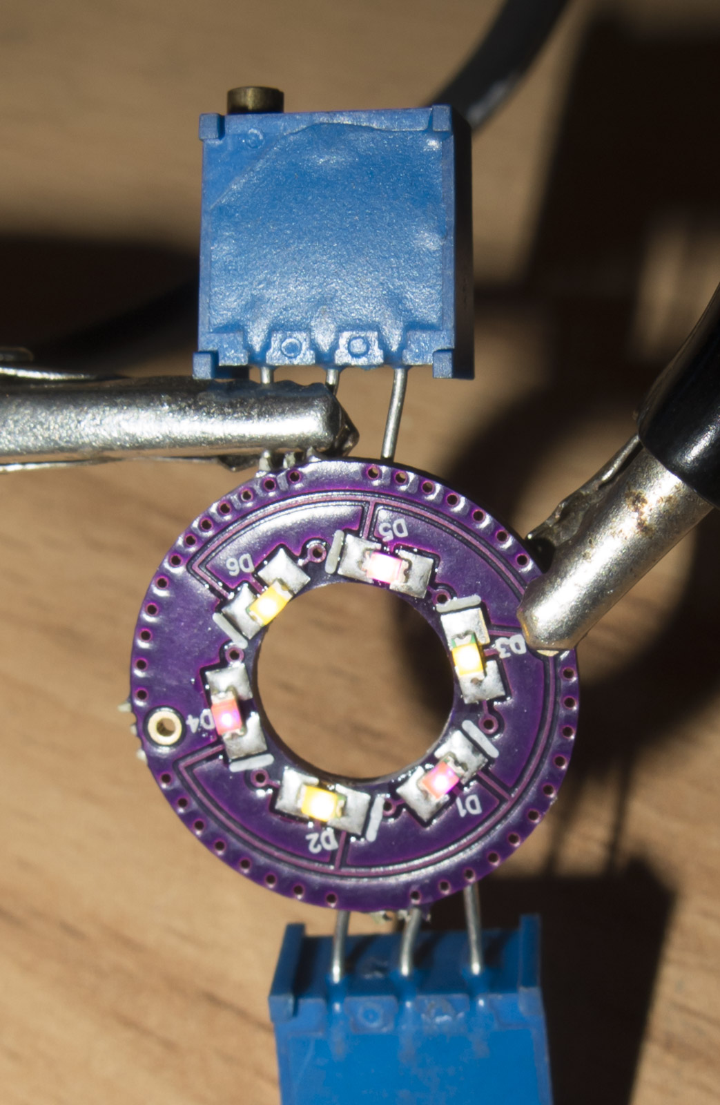
Tail board without balance resistors tested successfully
Pink and warm white in the 2 I tested
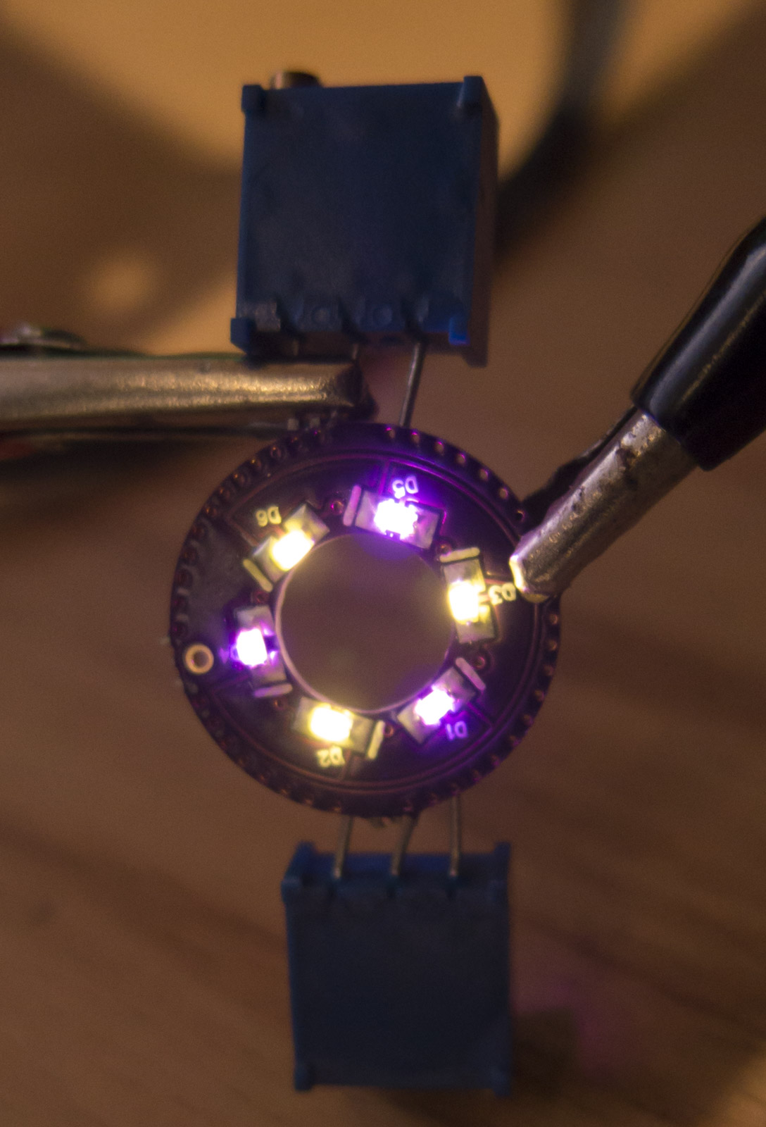
3x3mm Potentiometers will take a while from China
Have such boards ready but not yet the potentiometers
If you want very bright tail caps you have to go to Bistro HD OTSM drivers
I just want to say, “Don’t give up!”. I pretty much thought I should have yesterday, but kept tinkering anyways. According to the OP: “I’m sure there are some drivers that simply won’t work correctly at all after it is added.” I thought I found the driver/firmware that wasn’t compatible with a lighted switch.
This is what I was trying to add a lighted switch to: Moonlight Special 17mm Driver with the BLF A6 firmware.
I spent about 8 hours figuring out how to make this work. Part of my “fun” was when I asked my wife what color she would prefer in a tailcap. I had it working (for the most part) with yellow, but she thought green would look better. I found out that yellow is terribly inefficient - it requires a lot more current than green.
And in hindsight, green actually worked out better since I was not able to get yellow to work fully. I was able to get forward and reverse mode to work, but it never reset to no memory despite my efforts with various bleeder resistors. It always kept the reverse mode after it was turned off.
What was strange with this driver/firmware is that the normal 500-800 ohms for a bleeder resistor was not even close. I ended up with a 6.9K (22K and 10K ohms in parallel) ohm resistor.
Here are my notes testing the green LEDs, which shows my attempts with different resistors (I count 13 total):

Every attempt required me to solder a different resistor to the driver and test like this:

Here’s the resistor (combination) that eventually worked. Please note this is not the final installation:

Here are a lot of the resistors I was working with:

And finally, which makes this worth all the effort, here’s the switch with the green LEDs and a 47K ohm resistor:

I will post later once I get everything all cleaned up and put together. I’m thrilled I was eventually able to get this to work!
TA Bistro OTSM driver I build and sell have no problems with very low tail resistors, you could drive the LEDs with 5mA if desired
I also got a circular board that replaces the washer which makes a lot more light of the LEDs used
with 6 LEDs and has the option of 2 potentiometers as well balance resistors
In this picture external potentiometes as I am waiting for the 3x3mm ones to arrive
Pink and warm white
Wow, glad to see your persistence paid off!
I just built up about 10 this past week (Christmas orders for friends), but I have a pretty set standard for what I usually do. Typically just 105c drivers, Mtn FET+1, or BLF A6 drivers. I haven’t tried one of the OTSM drivers yet, but I’m sure they’re good stuff. And I always use the ring board that Lexel mentioned - those really do give good results.
Keep on modding!
Just FYI, GB sells a nice glowing tailcap package, including the transparent ring.

https://www.gearbest.com/flashlight-accessories/pp_1403798.html
Hello friends !
I ask advice how to make friends with six-voltage drivers type FX-6 , CF FX-17A , RNX-28A , FX-30 with illuminated buttons from OSH Park?
Hi johnkeyy68, I think that no one has tried it with those drivers, but it could work alright. If you try it let us know the result.
Already tried. I assembled the Convoy L2 with XHP 50.2 and the FX-6 driver. Two-channel board with OSH Park, LEDs nervously flicker
It is necessary to try the bypass resistor between the anode and the cathode, but with what resistance?
you need a bleeder of 1-2kOhms from battery positive to battery negative ground ring on the driver
Just noticed how much this has taken off! Lots of cool developments from Led4Power and others.
these will only work in convoy lights without the biscotti driver
With biscotti you just have to solder 1k resistor on driver.
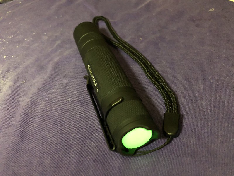
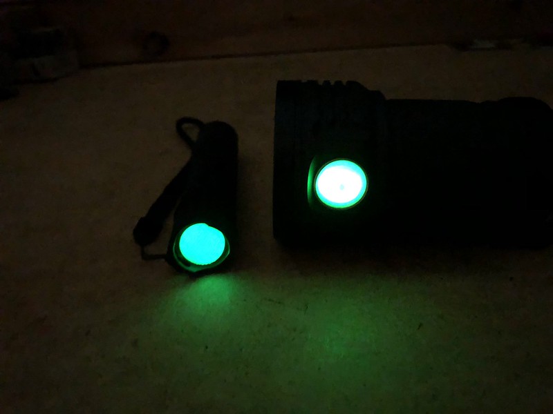
Here’s the final install of the green lighted switch in my Convoy S2+.
This is the 6.9K ohm bleeder resistor (4.7K and 2.2K in series) that worked with the RMM Moonlight Special driver with BLF A6 firmware. Certainly a lot higher than I would’ve ever imagined.


And here’s the 47K ohm resistor used in the lighted switch.

I measure 0.03 milliamps for the lighted switch. A lot lower than I was expecting since it’s plenty bright at night. Here’s how it compares to the Meteor M43 turned off (FYI, the M43 lighted switch gets brighter when the flashlight is turned on).
Here’s a link to my build in case you’re interested: Convoy S2+ Mod With A Lighted Switch
Wow, 6.9kΩ.
I’ve only tried less then 1kΩ on my moonlight V3’s.
So the reverse mode switching works?
Now I have to go through my 1206 and 805 resistors to find a 7kΩ-ish one.
Thanks.
Yes, the reverse press works as it should along with all the other functions. I kept experimenting with different bleeder resistors until I found the right value.
Got a few yesterday and they do work with the Biscotti driver and the BLF A6 driver as well, but it enables the next mode memory on those drivers.