This is a very powerful one, not cheap at all, but we target 8A for 6V LEDs, XHP35 can be as hard driven as desired
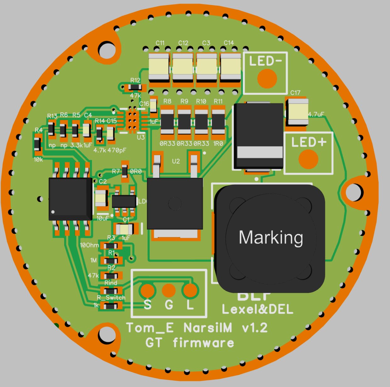
I got the board made in Diptrace I made improvements
power cap pad sizes increases to a 0805/1206 dual footprint, depending if 1206 fit to the driver cavity
other parts 0402/0603 Footprint
MCU/LDO caps 0805 size to use OTSM cap
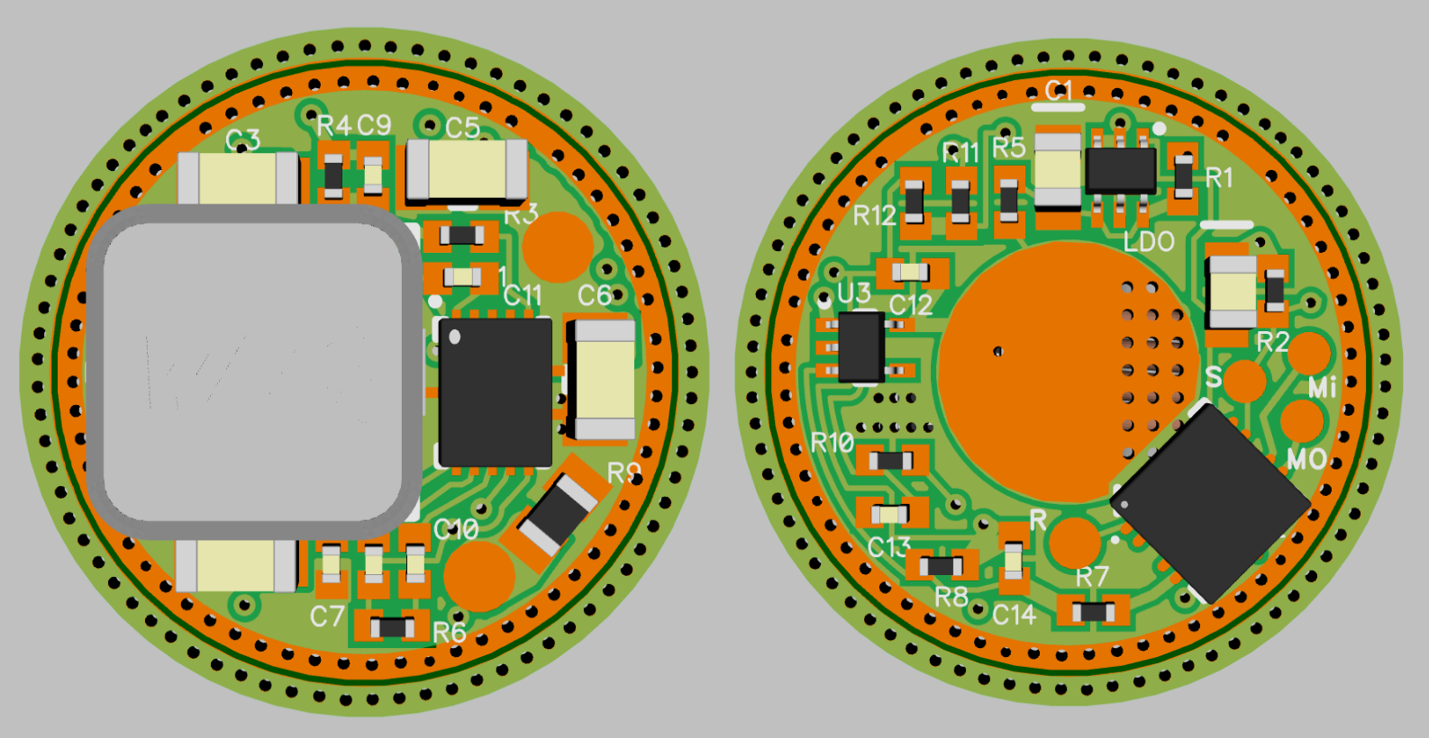
and especially the thermal connection of the boost Chip got improved massive using the inner layers with direct thermal path through viases
No place for programming visases so a solder pads or pogo pin connector plate
ignore the 2. ring around it its just for production on a bigger board for easier separation
Really neat work with the implantation !
That big square is the coil I presume ?
I know it’s early stage development but do you have a guess at how how much it could cost once assembled/programmed for a lambda Customer like me ?
Also a Narsil variant will be coming as well, just needs further testing of a low standby current precision OP Amp
The bare material costs on this driver alone will be about 14$ From Mouser
Lets say about 6$ for assembly, customer support and testing
For first 50 drivers likely about 3$ to cover development
Shipping will be more expensive than TA drivers as its more than 10mm thick packed 4.5$
Its a small powerhouse, but the regulator can pull up to 19A from the battery, which gives an impressive output on 6 and 12V
For Narsil drivers above about 35mm the GT layout is likely the cheaper variant with same output and better efficiency on this the components are almost as cheap as regular multi cell FET+N+1 AMC based drivers
That’s really impressive, it means 50W output would be relatively easy right down to 3V, which in turns means 4000+ OTF lumens whatever the battery level on a single 18650 with the right led configuration.
That’s better than any production light I know of if it ends up being produced I’ll definitely have to get one.
I am so excited about Schoki’s Boost driver I can hardly contain myself.
I have actually been collecting parts and am now starting to look for hosts for this driver. These will be the first real lights I have built in almost a year, there was just nothing to significantly upgrade from what I had before.
Now I have plans to rebuild most of my collection around these drivers. The XHP35 is better then the XP-L or L2 in every way, more lumens, more throw, no tint shift. Then you have the xhp50.2 and xhp70.2 for some big flooder fun.
I have almost talked Schoki into letting me beta test some of these drivers…
I have some question about further development of the Schoki’s driver….
1. We’ve seen GXB20 being optimized for 6V out. Lone oceans said that the driver would do 12V, but for optimal efficiency some components would have to be tweaked. Are there tweaks left to make the driver more efficient at certain output voltages?
2. How about low-profile inductors? Could they work sensibly with this driver?
3. Is there any component on the driver that supports temperature readout or are we back to the world of turbo timers?
1. If you have the driver configured to 6V, and you use the right parts from the beginning (with the output caps being able to handle >=20V), then you need to change two small resistors and the inductor to convert it from 6V to 12V.
The other way around, change the two small resistors and the inductor again.
To be honest, both inductor values work with both voltages, but the higher value inductor has a higher resistance, so it runs hotter. So just change the inductor for better efficiency.
2. Didn’t search specifically for low profile alternatives, but the XAL7030 is a lower profile version of the current inductor I’m using (XAL7070). 6V operation only then! Didn’t calculate ripple, but 1.5uH should do it (a bit lower than XAL707 with 1.8uH)
3. The MCU has a temperature readout. It is on the other side of the board, so we will have to set the maximum temperature lower. If that fails, the boost IC shuts off at 150°C.
That’s better than I expected, thank you.
Question…Lexel improved heat path from inductor and controller. Maybe it would be useful to review thermal path of the MCU as well?
No worries, the thermal connection of the MCU is pretty good. I made some new revisions of my board to make the heat path better. The board you can see in the thread was made to get a working board as fast as possible.
And remember, if the inductor and boost IC heat up, pretty much the whole board heats up, since those two parts cover a lot of surface area. And a 17mm diameter PCB is pretty small. So when those two parts heat up, every other part gets hot as well. And half of the MCU is directly under the inductor (and it’s a 4 layer board).
Just a suggestion: If you do not need all pins of the MCU (and you find the space), could you please prepare external pads for those? Maybe with traces to GND that can be cut when needed.
Yes, no firmware today supports NTCs but this may change quickly once they become more common, as on led4power’s boards.
You can solder small leads on the pads, you just need patience, and a fine solder iron tip. I mean really fine. Best you hold the leads down with some scotch tape while you solder them on. And watch out to put no force on the leads, or they could lift the whole pad.