Texas_Ace integrating PVC sphere with no math involved

I thought this same thing, which is why it took me so long to track down the issue.

I still can’t fully explain it but I know for 100% sure it is not the meter or any other aspect of the sphere except for the sphere itself.

I tried 3 separate meters on the sphere, they all read the same with a deviation as lumens increased.

I tried the same 3 meters on my PVC setup, they all read the same with no statistically significant deviation regardless of lumen output.

light leaking in is also not an issue as the sphere is contained inside a box plus the light in the room is nothing compared to a 5000+ lumen blast from a flashlight. Plus that would cause the readings to go up, not down.

The readings do deviate, the sphere itself is the only thing left that it could be as I have tested everything else in the PVC sphere. I still do not understand why or how it is happening, only that it is.
About the only thing I can see as remotely possible is if the light is heating the surface and this affects its reflectivity. I guess it goes in that category of mysteries along with many other things.

I agree that to see mod results made by the same person it’s enough but my post aims a more general situation. First, we’d have more info on the beam. Second, reliable measurements are important to compare different flashlights, measured by different people.

Like I said, to each their own.

Such measurements would be meaningless to anyone that was not intimately familiar with flashlights and those that are do not need such info as they generally can get all they need to know from a beam shot and basic numbers such as lumens and kcd.

Such a setup would be more precise, I just don’t see the need for such precision.

Hello TA, first I want to thank you for sharing your work, a while ago watching this post, I like the idea of building a spherical pvc like yours (excuse my English I use a translator), therefore I acquired a luxmeter there, I could Tell me what is the centering disc input diameter? I have available pvc pipe 4 “and what is the material that looks like foam? I have a friend who has milling machines, so I do not think it is difficult to center, well I do not bother you anymore, greetings !!

https://es.aliexpress.com/item/TASI-TA8133-200-000Lux-Digital-LCD-backlight-Pocket-Light-Meter-tachometer-luxmeter-Lux-FC-Measure-Tester/32625335050.html?spm=2114.10010408.1000016.1.l0Xr49&isOrigTitle=true

I used a 3” PVC pipe myself but as far as the centering rings for the flashlights the outside lip it just slightly larger then the outside of the PVC pipe so that it has a snug fit. It is easier to measure your pipe to get the exact measurement, I don’t know if the pipe where you are has the same dimensions as in the US.

The foam is exactly that, styrofoam. It was sold oridgnally to stick the stems of fake flowers inside of a pot to keep them standing up.

Although honestly lots of things could work, a diffuser film like DC-Fix should work as well, possibly better. Or really anything that fits in the area and diffuses the light.

I doubt you would need a milling machine for this but it would work if you have it, although a lathe might work better since all of the parts are round.

My centering discs are 3D printed plastic if you have access to a 3D printer. Otherwise you could simply use cardboard and cut the hole manually.

Hi, thanks for your prompt response, then have several disc centered according to the head diameter flashlight? My friend has both machines, lathe and milling machine, well at one time publish my copy of your device, greetings and thanks again!

Bumping this thread back to life.

I copied the design almost completely. I even ordered the same meter.

Changes i made:

  • Sanded the inside of the pipes with 400 grit to a matte finish
  • Don’t have a 3d printer, so i cut some chinese food container lids and used 3m adhesive to stick aluminum foil to the inside
  • Instead of foam, i cut a disc of acrylic to fit inside the opening, then applied two layers of white contact paper. A third brought the numbers too low. Now, they’re a tad high. I think i’ll hit the backside of the acrylic with some 2000 grit to see how close i can get.
  • I’m calibrating with a few well-tested lights, and going for the expected outputs. An olight m2r warrior and a nitecore p12. I’m hoping to zero in on the expected lumen outputs and call it good.

Thank you, OP, for the detailed info and the motivation.

Glad to hear someone is finding it useful.

Remember this is still a DIY sphere. I would not expect better then ~10% accuracy at the very best. Consistency is the most important thing with a standard calibrated device. Mine still reads the same (minus 3 lumens, which I expect is due to dust) 1.5 years later. So I am happy with the results.

What’s the difference between hs1010 and hs1010a?

Not a clue., I just got 2x of the cheap ones on ebay. Think they are the A models.

Here’s my sphere bleeding a bit of light with the q8.

Integrating sphere light bleed

Finally figured out how to post pics here. :smiling_imp:

Lower lumen lights are spot on, but as they go higher, results are lower than expected.

This specific light has 4 freshly charged 30q. The bottom pcb was replaced by a copper plate with 20ga turnigy bypasses and heavy springs. No tailcap loop for amperage (sorry). Highest this light has made was 5970 lumens in my sphere.

Even worse, was my L6 with MTN driver and 70.2. That light pulled 20.67a with liitokala blacks and only showed 8020 lumens in the same sphere. That light made a similar glow in the PVC.

I ordered a bottle of barium sulfate and will test later with that painted inside the sphere to see if I can decrease the bleed. I read an article that compared a few different ratios of paint to BaSO4, and i’ll likely use 20% or more powder to paint if it doesn’t turn into paste. I was intrigued by this article and plan on painting it with ratio of paint: https://www.triticeaecap.org/wp-content/uploads/2011/12/Barium_Sulfate.pdf

I really don’t want to have to use any type of multiplier if I can help it.

I have a few lights coming that I will test in my sphere and compare to TA’s numbers in his. I’ll post results.

Hmm, I just checked my sphere with the lights off and noticed that it does bleed some as well, I never noticed before since I always have my work lights on at the desk.

I actually have had some new ideas for this sphere design that should be even better but also a little more expensive.

Does anyone know of a cheap diffusing film/plastic? I am thinking about using a clearish diffuser could improve the consistency.

How are you calibrating the sphere? What kind of examples do you have in the low modes?

I’ll test on some low modes and add to my growing spreadsheet.

Here’s so far: https://docs.google.com/spreadsheets/d/1IbqSD4ovvGC_1MDzzlFbKf8t38Q8j1wkuu8g_Q27jPk/edit?usp=sharing

I was thinking about this myself. We need something that can completely eliminate the beam shape going into the measuring device. You don’t want a skinny beam (thrower) to read any differently than a wide beam (flooder). We need something to neutralize the beam shape and do it better than tissue paper or foam discs.

I believe that’s the point of using a dome shaped ball like a true integrating sphere, but with pvc tubing, we lose that effect and need to compensate.

One other issue I want to work on is sealing a flashlight to the measuring device.

I have a question for those that are experienced. How important is it to have the light source, the actual emitter, on the same exact plane when measuring the lumens?

Obviously a deep reflector like on the GT will push the emitter farther away from the measuring device compared to say a MF01 which has many little emitters less than an inch from the lens. Does this difference in depth effect the readings?

If so, should we make a flashlight mount that has an adjustable depth to it so we can keep the emitters of all our flashlights on the same plane?

Yeah, the best idea I have so far is using the diffusing panels from the florescent fixtures you can get at home depot, a few stacked together should remove all beam pattern from the beam. Although I know a better option has to exist.

The sealing of the light to teh sphere is very important, I use a bunch of 3D printed rings to seal to various lights myself. When they do not seal properly there is a noticable drop in lumens.

The emitter distance is not that important but the black of the light entering the tube can also have a very noticable effect by absorbing lumens. You want the very end of the light inside and that is it.

Sorry for refloating the thread after so long but I can’t find anything on the internet that I see feasible or easy to implement, the wait is easy but I’m not convinced it seems to change depending on how you put the flashlight.

In your case it doesn’t change anything with this design, I know it will have taken a long time to fine tune.

In short I want to mount one and your design is the one I like the most!

I’m not looking for precision, I’m looking to know which light shines the brightest and how much difference it makes.

I can also use an S2+ SST40 convoy as a reference light.

I was using the mobile but I don’t like it depending on how I put it changes and a lot.

In Spain the closest to 3" pvc tube is 80mm a little bigger.

Would 80mm diameter be a good option?

The HS1010A meter you use is quite old.

Is the HS1010A still a good choice?

It is very inexpensive and on YouTube I see many use it for flashlights.

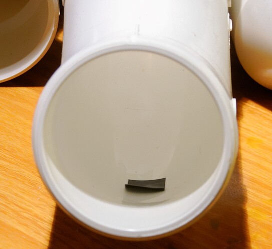
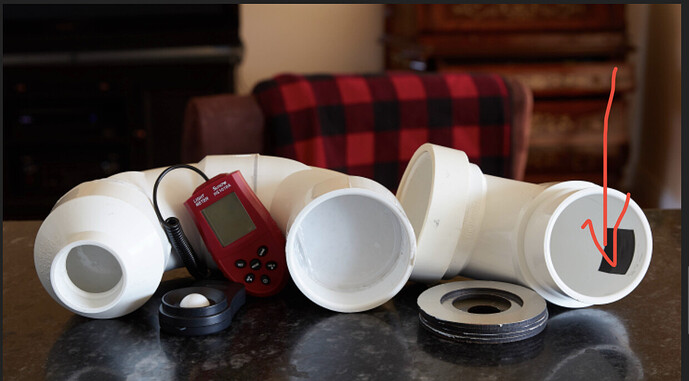
Also know how to use that piece of black duct tape, it only puts a 20mm piece, curious.

Lastly what it says in front of the flashlight is it just foam, like the ones they use in packaging, some flashlights are sent with white foam but it is thinner.

Or am I looking for something special?

Thank!

Edit: Is the piece of electrical tape put on the starting tube of the flashlight or on the end tube where the meter is?

This was the prototype, I tweaked the setup later when I started making them for others

The HS1010A meter is used simply because it is the only meter I could readily find that was easy to mount to the end of the PVC pipe without a lot of extra hassle. They work good enough for these purposes in my experience, the biggest weakness is like most low end meters they will ready cool white lights higher then warm white but it is consistent.

The size of the pipe really doesn’t matter.

The tape is used for the final calibration fine tuning based on the calibration light.

Thank you!

I have been looking at the information but I am not clear where the electrical tape goes.

On the flashlight side or on the meter side.

I’m guessing on the flashlight gap side so it adsorbs the beam.

Edit: it is placed in the first joint to the second elbow.

It actually doesn’t really matter where it goes, the system is sealed so it will effect the readings basically the same regardless. I put it on the first piece since that is the only one I don’t glue together.

I can’t calibrate it until everything is fully assembled as the readings will change during the assembly process, even 1mm can change them a surprising amount.

1 Thank