Answering comments:
Thanks FPV. Yes once I finish the firmware and done some proper field operation and stress testing, I'll put everything online so you can order your own PCBs and put your own together! However do be warned that you do need some sort of proper setup to either reflow / hot air this or put this together under magnification. Meanwhile I'll start putting up my GXB172 page on my website as I go along.
As for sales, we'll see how it goes! I certainly wouldn't want to put something up for sale if the firmware is not up to scratch or if the driver has issues. Suppose all is sorted out, I might do a small run, or send for PCBA which would be much nicer, but it depends. Morever Schoki / Lexel are already working on driver and it seems they have more history of releasing drivers, so you can go with that route as well! I just had no idea it was already in development when I made the GXB172.
KawaiBoy1428, whoops I meant to say 16V, but yes it's good for driving LEDs like the XHP35 (12V+), and by extension, also good for 9V operation. I do hope to make a 20mm version with even better performance (better passives) in the future to replace my GXB20, but I'm not planning to make this design any larger. The reason being that any larger would allow me to use an external FET solution and it's really much easier then to make a 50W or even higher power driver - no need to constrain myself with this particular topology. That's the good thing about the 'dev-board', easy to do tests like this.
Kiriba-ru, you are absolutely right! The driver and LED setup for any flashlight that can accomodate a 17mm driver would definitely overheat at 20W, much less at 50W! Drawing this amount of power from a small cell is also ridiculous. However, that's the premise of the project - to make a ridiculous driver. As I've mentioned, it's fairly useless from a practical point of view, but practicality was not the main point of the GXB172, at least not in 50W output. I have no illusions that 50W is anywhere near a practical drive power for a 17mm-driver flashlight. 
Regardless, the driver should still be in the upper 90s% for most of the range from ~100s of mA to 2-3A output (will measure soon) so it's still a fairly efficient driver at realistic drive power.
For example, the Emisar D4 has a 3000+ lumen direct drive mode, but this lasts for only 10s of seconds, before the light drops down steeply to some ~300 lumens or so by thermal regulation (based on here https://www.youtube.com/watch?v=GVj7NnAj_Ps). Again depending on what you set the thermal limit to be and what the external temperaturate is, my guess is that the Convoy S2 can probably only handle on the order of 3 to 5W of continuous run time (e.g. headlamp), and likely not much more than 10W (handheld light) for any reasonable temperature limit (taking into account the whole system including LED, driver and battery).
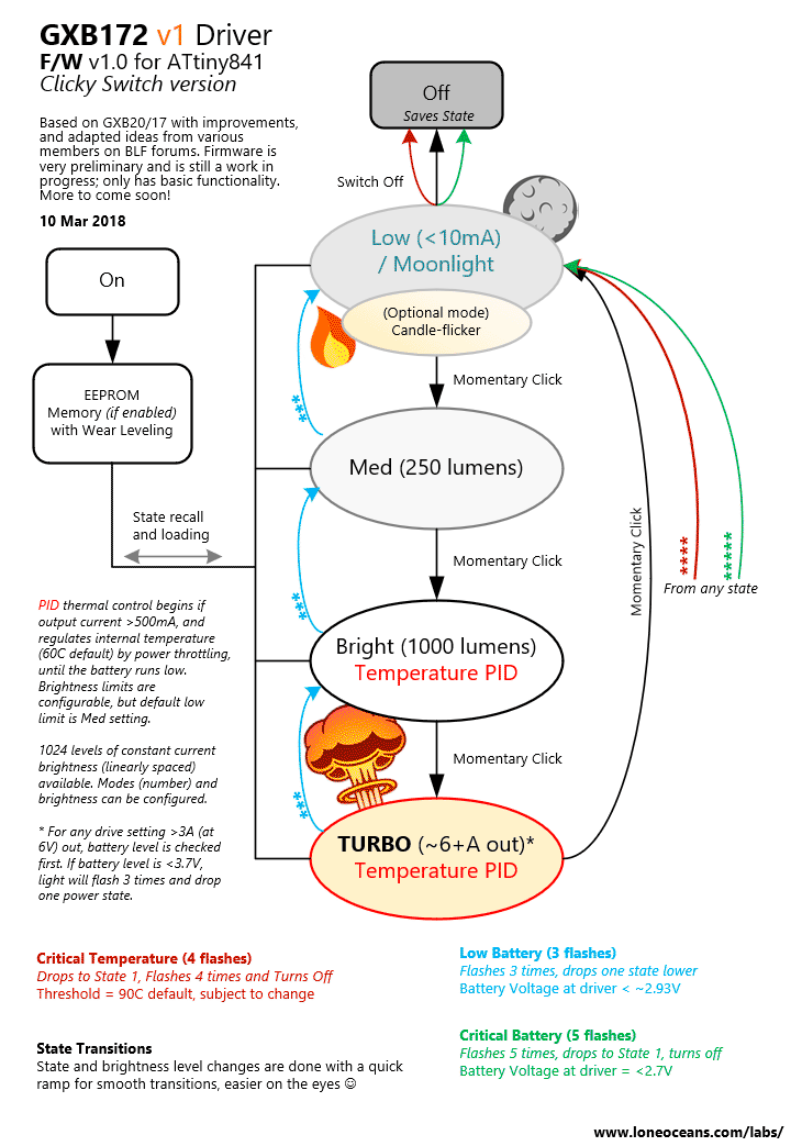
And as Schoki said, because the driver is in fact much more efficient at lower drive power, this makes it a pretty good driver for 20W operation I think. In fact, in real life, I'm going to set my everyday mode limit to be around 25W operation. This is very easy to set and the 1024 current limit steps make brightness control still fairly high resolution even at lower powers (or you can swap out some resistors to make this even better!). I'll be able to do some more detailed thermal analysis later, especially when I get it into form factor.
Also Schoki, thanks for your comments, and I see the renders of the driver Lexel posted! Is that the driver you two are working on together?
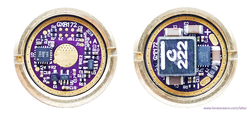
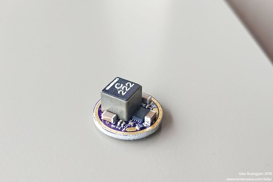
Yes I agree the top (inductor side) layout looks similar, but I guess come to think of it it really falls out into place just based on how the (few) power components and traces needed to be laid out, and what we can fit into the same round PCB. I did start layout based on the reference layout in the datasheet, and used a single 1210 capacitor for input and output rails, but I couldn't get it to fit in a reasonable way, so I split them into combinations of smaller caps instead and that's basically the only way I could lay it out. The rest of the compensation network and feedback then just slots in the leftover space. I also initially use through-holes for the LED outputs but I switched them to large pads instead just to make routing on the other side easier. Also good catch on the max voltage rating, I meant to say 16V!
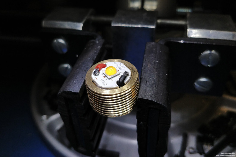
 , since heat will be the biggest issue. However, this is intentional! Moreover, it will be able to drive 50W for a short period of time, before thermal regulation kicks in; and if you turn it down to say 10-20W, then you've got a much more practical but still powerful driver. I've got a prototype PID thermal control firmware tested and it seems to work OK, just need to put it in an actual light to fine-tune the variables. However, you're right that the C8 is likely one of the larger lights that still uses a 17mm driver. I'd imagine that having a C8 and swapping out the XPL HI with a XHP35 HI would produce some pretty nice results , even if the XHP35 HI die is a little bigger than the XPL HI.