Should I open new Interest thread? Because I'm not sure how relevant is current list, there is possibility some members gave up after lack of activity in this thread.
I think that if the board is available, people who are in the list will just pick up their Q8 and start modding it. And I think that with the first succesful mod come new people buying the ledboard. Especially with ready mounted Luxeon V’s, the mod is doable for many many people: instant 8000 lumen in good tint (well, if the center pieces are succesfully reamed :innocent: ).
I guess I will have to unsolder the ledboard on one of my Q8’s and do some measurements on the hole positions. In TA’s design the two small screw holes were dismissed because they did not fit in the 4040/5050 double design, but who knows you can squeeze them in.
Would it make sense (or even be possible) to use rotated LED pads?
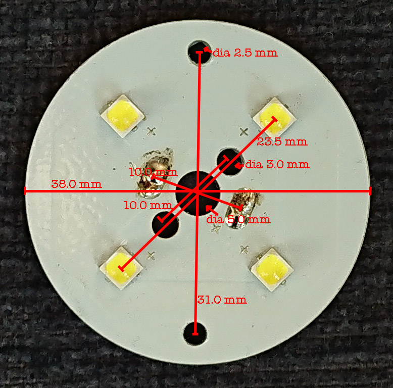
All fresh measurements on a production Q8 board:
Thanks!
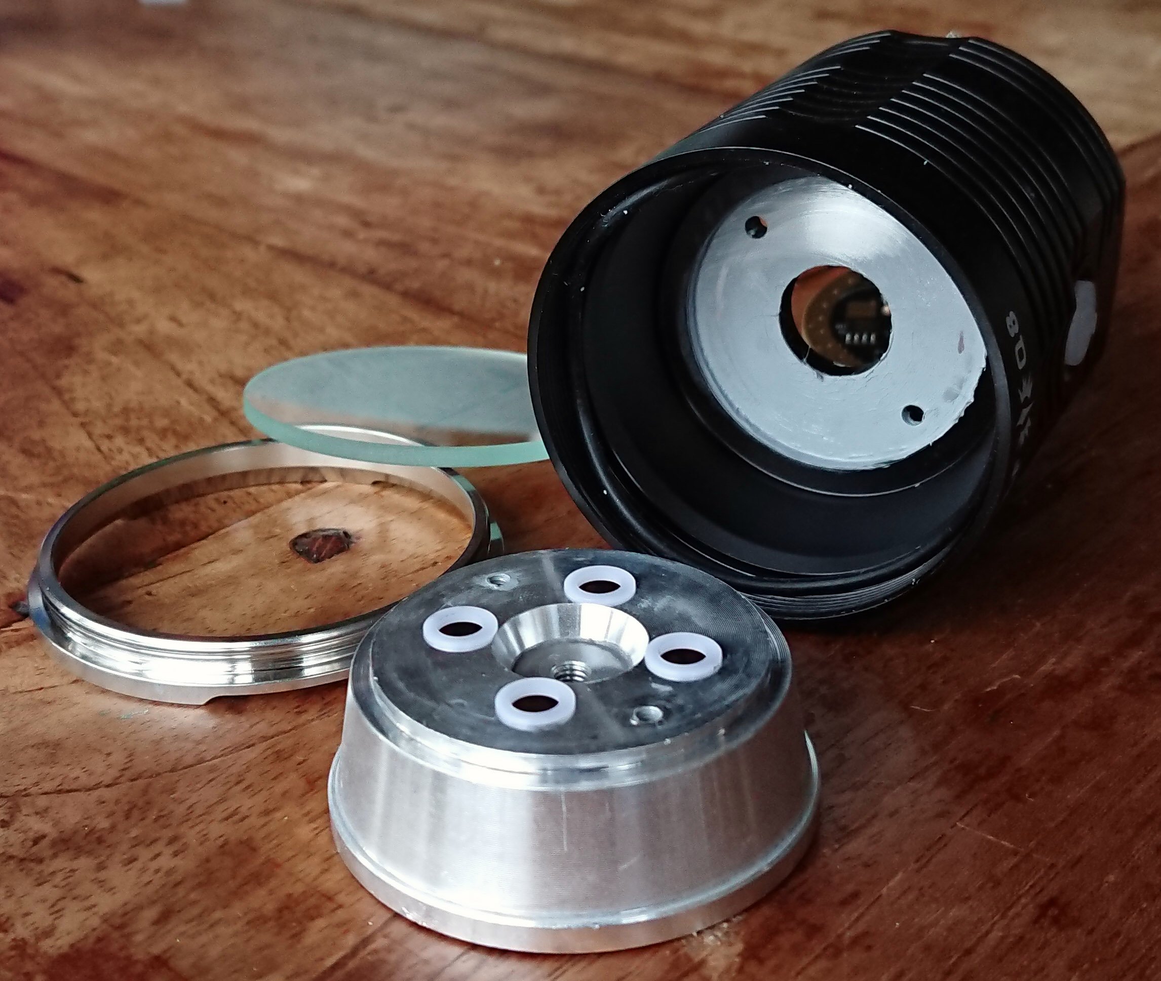
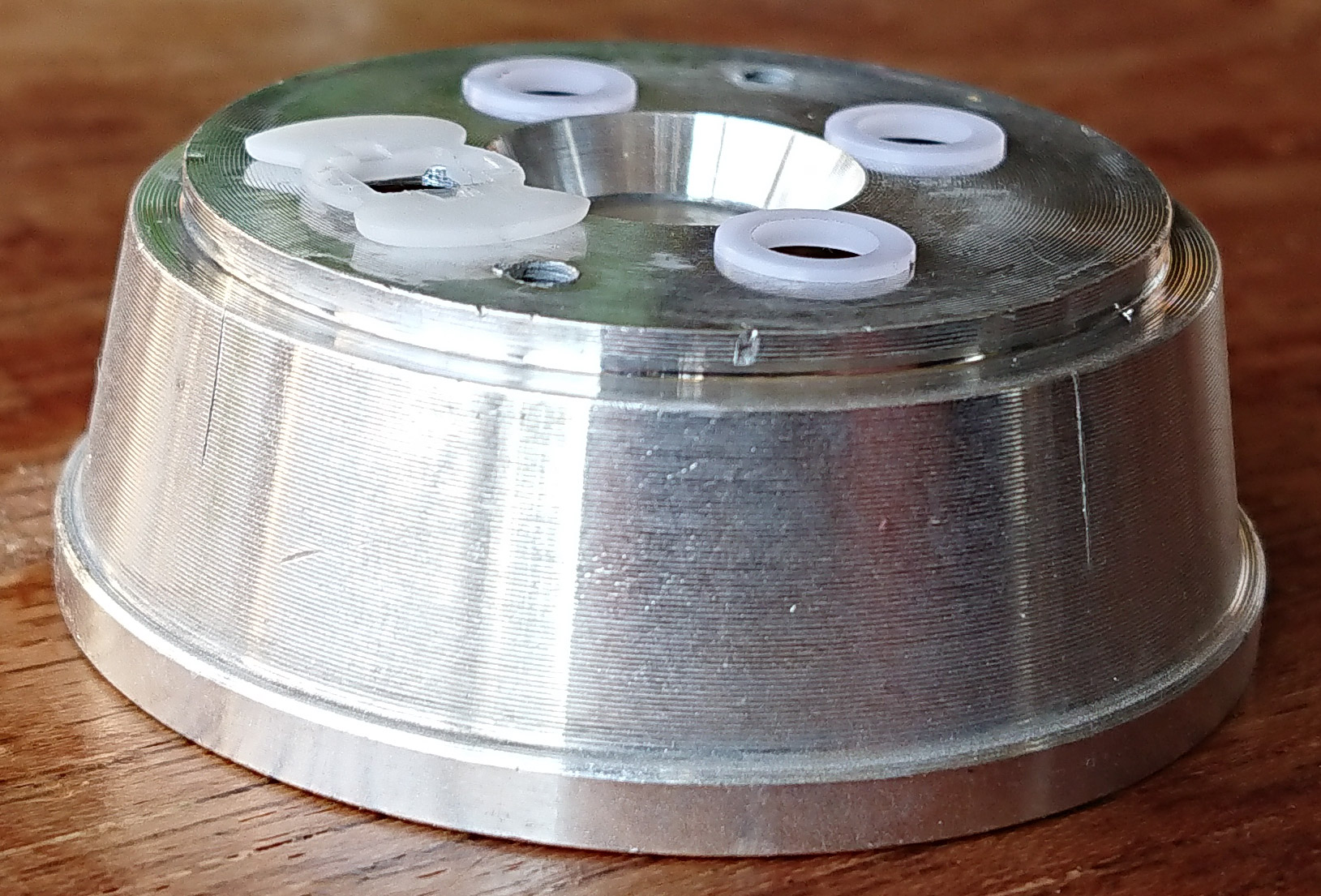
What are those two smaller center holes for?
They are for the led wires.
The two small holes further out screw the board onto the shelf in the first production run, in the later production run they allow longer screws from the underside of the shelf through the ledboard into the reflector (clamping the board between reflector and shelf). In both cases they prevent twisting of the board when closing the bezel. If you leave those holes out, clamping of the ledboard to the shelf is leftover to the bezel, while risking twisting the board with closing the head. It will work but it requires some care when closing the head.
Central hole is used to clamp PCB+reflector to body?
Central hole is “only” to coamp PCB + Reflector together. The body/shelf diameter is much bigger.
I thought I can rotate LEDs around PCB center so I can fit both 4040 and 5050 on one PCB without interfering with screws, but I can't because screw cavities in reflector allow for only one position (45deg).
There is one solution - using flat countersunk screws for PCB clamping, is that ok?
That means pcb must have countersunk holes, but I think it's doable by factory.
Except that in all but the first 500 Q8’s the holes in the shelf do not have threads.
Edit: the first 500 may not have threads either but the screws were just forced in.
Edit2: can someone else help out further?, I’m rather sick atm, need stop doing things for a while.
Interest list updated. Current to here.
led4power, thank you for looking into this and hopefully taking it on!
firedome, how many boards are you interested in? You have a post at 60
and a post at 88 :
You are currently in the list for one.
For the first 500 flashlights, the Screws holds the MCPCB on the shelf/head of the Flashlight.
On all other Q8, the Screws go throu the shelf, the MCPCB and screw into the reflector.
I would say, do not care about the first 500 (I have two of them and one later Q8) and make 4 holes near the LED-Pads.
For the first 500 everyone have to find a solution, e.g. with countersink screws, or without screws (clamping all together with an adapter/old mcpcb over the centerscrew of the reflektor).
Yep, same thing I found when trying to keep the screw holes. That is why we decided it was best to just leave them out.
Sadly we never did find a good option for keeping the screw holes and the double footprints. The dual footprint doubles the market for the mcpcb’s so that was important.
The best option was to use a washer and a longer center screw to sandwich the reflector, mcpcb and shelf all together. This is ideal IMHO.
You could even sell the washer and longer screw with the mcpcb to make it super simple.
This is what I would do if I were you, I prefer the reflector provide the clamping force anyways, it is a more even pressure.
I was on the list for two boards, I’m still interested.
If both footprints are not on the same board, I would like 1 board for 4040 and 1 board for 5050.
Thanks djozz, but what is purpose of big central screw in this version? Two small screws clamp everything anyway?
Currently, I see 3 solutions to dual footprint-screws interference problem:
- Using only central screw and washer like TA said, problem is that it doesn't protect pcb from twisting,
- Making separate mosX pcbs for 4040 and 5050, but they are 1.55mm tall, would be that a problem?
- Making just 4040 Cu DTP version, but I'm not sure about percentage of people form list that want 4040 vs 5050?
Do XM-L size LEDs fit without reflector modifications?
Big screw clamps reflector to pcb from backside.
Reflector openings are 6.5mm (according to the drawings from CAD files that were shared by Miller).
That big screw does not much, except fixing the ledboard to the reflector, in the first run it probably helped fixing things in place during assembly to prevent shearing off leds. It is something that Thorfire came up with, it was not how I designed it in the first place and we just left it because we could not see harm. And now it comes handy to fix the whole thing with the washer if the small screw holes are left out. I think that will work fine without twisting becoming a problem.
The reflector base is a bit wider than the cavity in which the MCPCB sits. That cavity is 2.2mm deep, so the 2.0mm board is sunken in by .2 mm. The base of the center pieces is .5 mm, so you have .3 mm room to play with, a bit less because the reflector is clamping on the centerpieces, squeezing them slightly I guess. In any case, you will not get away with a 1.55mm MCPCB.
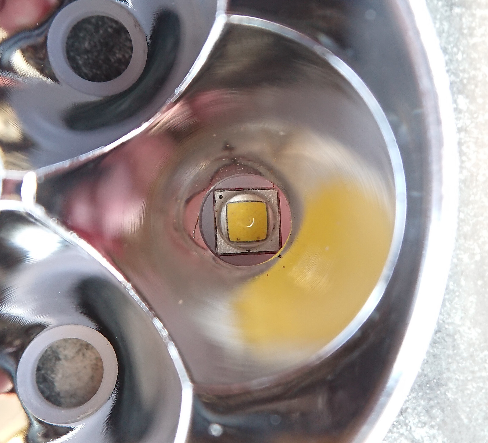
I guess no one has checked the fitment of XM-L leds before? I just did: by just a bit a XM-L does not fit the reflector holes. But the fix is easy if you have a reamer (a few dollars on Banggood gets you a reamer thst does this job fine).
This is the stock reflector opening that does not fit an XM-L2:
Some light reaming makes it look like this:
Now a standard XM-butterfly centerpiece fits and the reflector is XM-L2 ready.
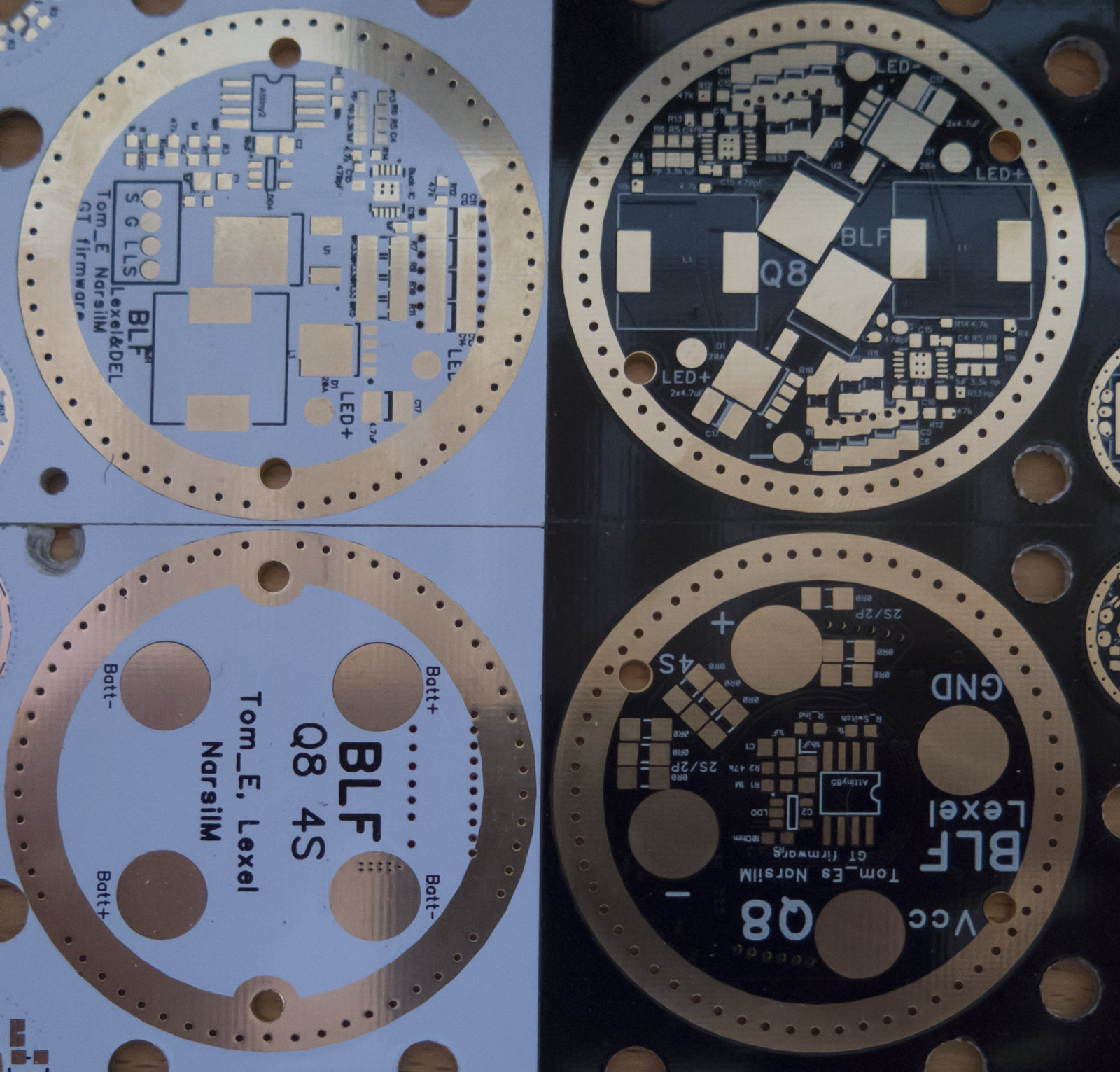
Buck drivers ready