Review: KD 7135 V2 drivers 3040/2280/1520 mA with mode configuration

E1320 said:

Good news I just got a chance to take apart a Shiningbeam P-Rocket and it had one of these new drivers and I was able to reflash it with the standard setup I have been using on the old Nanjg drivers.

Are you sure it's the same board? It seems to have a quite different pin layout; others said so, too.
Or did you refer to the PIC version of the NANJG105(A)?
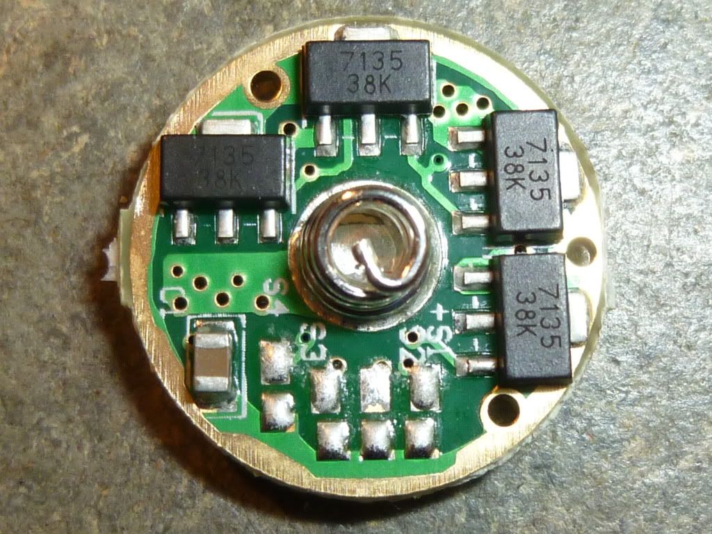
Can you take a photo of the driver?

Hi,

New to this forum, and flashlight diy projects. But I like it already!

I'm thinking about using this driver (2280) with a 16340 battery, and a suitable xm-l led (something like http://www.dealextreme.com/p/xm-lt6-885lm-led-emitter-6000k-white-light-bulb-3-0-3-5v-50599 ). What do you experts think about that?

Welcome! IMO you’d be better off with the 1.5A version of this driver if using a 16340, especially if you are using a non-IMR cell. (IMRs are more suited for high current than regular (LiCo) cells). I tend to be on the conservative side, so others may disagree.

Last night I put a 2280 into my Yezl Z1x (UF2100) and boy does that get warm quick. I don't know how you guys with DD drivers in those things handle it.

Thanks mitro! Aside the heat, are there any serious cons with my configuration? Guess battery time will suffer, but if I use aw imr battery and doesnt run it on hi mode all the time it shouldnt explode, or burn the led or something like that…? I think it could be a pretty powerful torch!

I have 5 of these winging their way to me.

I am very interested in learning how to re-program this driver.

What equipment and software would I need in order to do this?

Many thanks

I haven’t tried yet, but with an “Arduino Duemilanove” and a “Soic 8 Clip” I think it’s enough. Look for them at eBay.

Thanks FX-32 I will check them out. Edit: Is there any chance you could give it a try and see if it works?

Does anyone know of a budget 3xAA host for these drivers?

Has anybody taken a picture of one of these after modifying for a mode group or feature? Do you just bridge the gap as if a resistor were there?

http://www.intl-outdoor.com/c8-module-xml-t6-led-amc17358-driver-p-261.html

See JohnnyMac's SAIK-305 mod here. Might be a little more modding than you wanted, I don't know. I too bought this light to do the same thing.

-Garry

Thanks, Langcjl, but that's a 105C. I know how to do those. These KD ones are a little different.

Thanks for pointing this out Garry. It is definitely interesting. While I really appreciate JohnnyMac's work, this solution involves too much heavy modding for me.

**Solarforce, are you reading this?!**
There is a massive gap in the market for a 3xAA P60 host with the same configuration as the Saik SA-305, using a 3xAA cradle.
**Solarforce, are you reading this?!**

I'm not much of a fan of it, but the Dereelight Javelin with the extender seems like the better option for me.

While also being useful to me; this driver is screaming out to be gifted out in a 3xAA host to friends/family (non-flashalcoholics).

I did realize that after I posted. This one is just two little solder pads that have to be bridged. I had a heck of a time doing it but it should have been really easy.

I really like this driver and have used a bunch of them, the only problem I have is that the tiny spring will give fits in some applications. Sometimes I have to stretch the spring to make contact. The last setup I had trouble with was a SF L2T. I tried all of my longest batteries and it was still too short. The spring is very stiff so I dont just pull it to stretch it. I bend each coil up one at a time.

Just to double check before I make a mistake when mine arrive.

If I want Low > Med > High, I would solder S2 and S4

And for memory just solder S1 as well?

FX-32 wrote about reprogramming these:
> I haven't tried yet, but with an "Arduino Duemilanove" and a "Soic 8 Clip" I think it's enough.

I still need confirmation that someone really reprogrammed this driver - and how exactly. It uses a different micro-controller.

Exactly!

What do u do just put a bead of solder on top of each or do u connect them to something? Thanks

Each of the solder pads S1, S2, S3 and S4 has an adjacent pad connected to the outer ring (connected to battery minus) -see picture.

Notice that S2 is situated just below the center of the spring (badly marked).

Just connect pad S1 to its adjacent pad with a blob of solder if you want to activate S1 (memory). The same for the other pads.

[EDIT] changed 'opposite' to 'adjacent'. Sorry, english is not my native language.

So in that picture, none of them are actually connected, right?

So connect the pad behind the pad to activate?