Thanks, Langcjl, but that's a 105C. I know how to do those. These KD ones are a little different.
Thanks for pointing this out Garry. It is definitely interesting. While I really appreciate JohnnyMac's work, this solution involves too much heavy modding for me.
**Solarforce, are you reading this?!**
There is a massive gap in the market for a 3xAA P60 host with the same configuration as the Saik SA-305, using a 3xAA cradle.
**Solarforce, are you reading this?!**
I'm not much of a fan of it, but the Dereelight Javelin with the extender seems like the better option for me.
While also being useful to me; this driver is screaming out to be gifted out in a 3xAA host to friends/family (non-flashalcoholics).
I did realize that after I posted. This one is just two little solder pads that have to be bridged. I had a heck of a time doing it but it should have been really easy.
I really like this driver and have used a bunch of them, the only problem I have is that the tiny spring will give fits in some applications. Sometimes I have to stretch the spring to make contact. The last setup I had trouble with was a SF L2T. I tried all of my longest batteries and it was still too short. The spring is very stiff so I dont just pull it to stretch it. I bend each coil up one at a time.
Just to double check before I make a mistake when mine arrive.
If I want Low > Med > High, I would solder S2 and S4
And for memory just solder S1 as well?
FX-32 wrote about reprogramming these:
> I haven't tried yet, but with an "Arduino Duemilanove" and a "Soic 8 Clip" I think it's enough.
I still need confirmation that someone really reprogrammed this driver - and how exactly. It uses a different micro-controller.
Exactly!
What do u do just put a bead of solder on top of each or do u connect them to something? Thanks
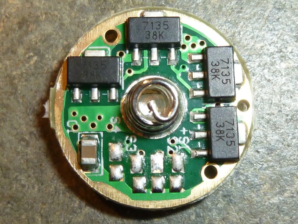
Each of the solder pads S1, S2, S3 and S4 has an adjacent pad connected to the outer ring (connected to battery minus) -see picture.
Notice that S2 is situated just below the center of the spring (badly marked).
Just connect pad S1 to its adjacent pad with a blob of solder if you want to activate S1 (memory). The same for the other pads.
[EDIT] changed 'opposite' to 'adjacent'. Sorry, english is not my native language.
So in that picture, none of them are actually connected, right?
So connect the pad behind the pad to activate?
Correct, but they have been when I tested it (residual solder on the pads).
The upper pads are S4, S3, S2, S1. The lower pads are their adjacent pads and are part of the ring. A connection would be a small vertical line connecting an upper and a lower pad. (I don't know how to paint over the picture). Is it clear now?
[EDIT] changed 'opposite' to 'adjacent'.
I received one of theese a few days ago, and now the included instructions match the mode selection table in the OP.
The instructions also advise applying thermal epoxy to avoid thermal protection kicking in prematurely. What is anyone's experience in this regard? I would rather skip that messy step... 
The last one i did i did not add any and it works fine but it is a V1 and its only used for short burts, i use my big guys for the long hauls

S1 & S3 bridged/
wanted to add pic of firefly mode

sc600 L turboX M F15 R
beams are dimmer thann pic. Zl lowest then 47s then TF.
So lower modes are PWM, but on high ti is current regulated?
Yes, you can use 26650 Li-Mn and have not more mA. ;)
I will be annoyed if so, no PWM is the reason why I bought this driver. KD state that all modes are current regulated.
All 7135*8 are current regulated. They are current controlled on High mode and PWM on Medium an Low. A difference, regulated - controlled. They want to say constant current.
This driver using the 380mA chips seems the same.
I got mine in the mail today, they are tiny...
My soldering iron is way too big to even attempt it and I doubt hold my hands steady enough to hold the soldering iron anyway.
Or maybe I can find smaller tips but there isnt any electronics shops around here.
before I got an iron w/ small tip I would do tiny stuff by stripping more of the wire, putting a little blob of solder on the end of it, putting that in place and then holding the iron onto the wire as close as i could get to the blob...
and, as for pwm - i must be the luckiest budget light guy, w/ respect to pwm - i have to try to notice it and it doesn't bother me (though, I'm sure I haven't seen the worst stuff that's out there...)