Awesome. Thanks for sharing! That Driver and Dimmer look so interesting!
I have added a clickable table of contents to the first post to make finding things easier.
Also, here's another beamshot (240m - 787ft). This time it was raining:

Finally it's done!
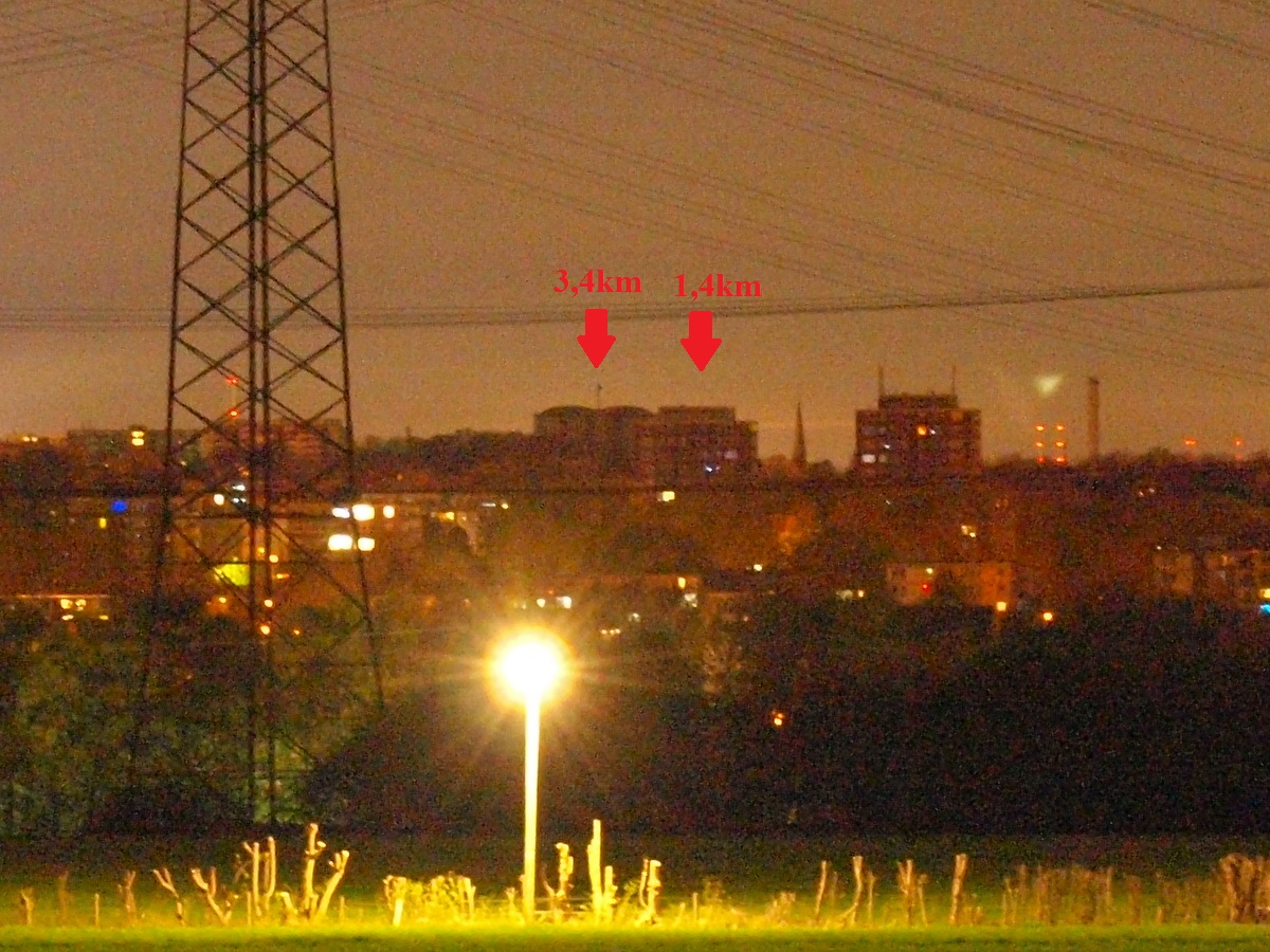
Beamshots in 3.4km (2.1mi) distance!
The conditions where very good which allowed me to make the beamshots I have been wanting for quite a while (ANSI distance of the light or further). They were taken with an Olympus E-520 using the following settings:
- Aperture F/8
- Shutterspeed 30s
- ISO 1600
I purposefully overexposed them to allow for viewing under daylight conditions (in reality the sky was dark). The target is the water tower to the left of and behind the building (which itself was 1.4km away) in a distance of 3.4km.
14mm:


42mm:


cropped:

Gif:

Some more fuzzy smartphone pics:


Cool!
![]() nice.
nice.
Really, really nice ![]()
Thanks again guys! ![]()
I think these might be the last ones for a while. The long distance ones where always my goal.
Maxabeam Gen3 @75W vs Project Excalibur :

270m:

impressive light!
Fine craftsmanship + advanced skills = near-priceless tech.
Respect.
The Osram Black Flat that is currently in the light has started to become damaged. There is a black dot in the middle that is growing over time when the light is used. To recap, this led has it’s maximum brightness at 4.45A (tested on a large, passively cooled heatsink) and it’s driven at 4.5A in the light. I sometimes run the light for longer periods at max output.
My plan is to put the new Osram Boost HX LED into the light when it becomes available. The light was designed with such a high-current LED in mind (driver goes up to 12A, lots of mass). Using a more conservative current (6A-7A?) and advanced heatsinking techniques (soldering the led with Indium, liquid metal thermal paste) should ensure that the LED never dies again. With a bit of luck the luminous intensity should stay the same and not drop as much when the light is running.
The wider beam with at least 50% more lumens will be more visible making the light more impressive.
The black spot forming is usually because the emitter got something on it, a spec of dust, oil from the hands, a bit of thermal compound or a splash of flux from soldering… something on the face of the die burns into it when running and ultimately kills it. I had this happen to two emitters in my 17 emitter monster, had to disassemble it and replace them which was not easy. Totally understand how it feels, so disappointing but in the end it can be a good thing as we learn along the way, right? ![]()
I need to learn to anodize without ruining the parts I just made… ![]() Your light is very nice looking, bet you can’t wait to make the new improvements.
Your light is very nice looking, bet you can’t wait to make the new improvements.
Yes, that is also a possibility. In this case the spot is exactly at the center of the die where the highest temperature is reached. I think the LED is overheating by quite a bit. The strongly degrading brightness that I measured (down to 70%) also points to this conclusion.
Most people use this LED in smaller lights with DD drivers. The current falls quickly in those lights. In my light the LED is driven slightly beyond it’s absolute maximum continuously until the batteries are empty (2h).
I think I need to be much more conservative regarding the current.
Is the MCPCB isolated from the copper pillar? The Black Flat requiring isolation from ground due to the negative lead sharing the ground pad is problematic when trying to keep a good thermal path, I’ve found. My answer is to glue the MCPCB down with Arctic Alumina Thermal Adhesive, it allows a good thermal path but isolates the current. That or re-flow the MCPCB to the copper sink and just use direct drive with the current limited, no modes….
Could this be from that laser you had pointing at it? Or was that a different LED?
No need for isolation. My light was designed for this. Thats why we used a battery carrier that has both contacts on the same side (thus no current flows through the flashlight body).
No, we would never use a cherry picked LED for such testing.
why not use a white flat for it?
link to that LED you mean
I see, good thinking. ![]()
For more beamshots, have you considered having someone operate the light from a set point and you, with the camera (or the other person) go to a different position closer to the target area for a closer picture of the object being lit from afar? It really makes a difference to see the object from fairly close, with light on it from a long way off. I did this with a water tower and my wife ran the flashlights, just amazing the effect. (Illuminated the water tower from 1.9 miles)
This was a 2 photo comparison to show the difference between a warm white and a cool white (yes, 2 lights), in a light misty rain. I was positioned about 200 yds from the tower, wife was 1.9 miles away to the left and behind me.
Because the Boost HX is a better version of the 2mm^2 White Flat. Is tolerates higher currents because of its larger package (lower thermal resistance). Upgrading my light is costly and requires a lot of work ((dis)assembly, cherry picking the led, focussing etc.).
Here a German description.
@DB Custom
Interesting idea. Maybe I will try that at some point. ![]()
Your thermal design through that copper rod is already pretty restrictive, a 1mm white flat would probably perform much better than a boost HX due to the current the boost HX will need to match its intensity.
Unless you just want a brighter beam with more lumens, then yeah the boost HX is a better choice.