Another great BLF innovation.
I tried this on a Convoy S2+ with 18350 tube. Took awhile to get the right combination, thought I’d share what worked for me.
I’m using a BLF X6 driver that comes with a attiny25 and Bistro as the UI.
I used the lighted tail switch from fasttech.
The driver has a 470 ohm bleed resistor already installed. The lighted switch has 2- 330 ohm resistors and blue led’s already installed.
These two together would not work correctly running Bistro. It couldn’t detect the off time, no memory and no medium press.
What finally did work, using the 330 ohm resistor from the switch on the driver as the bleed resistor and changing both switch resistors to 10k.
The” banggood lighted switch”:Astrolux SC / SS / S2/S3 BLF X5/X6 Taschenlampe 2 LED Beleuchtung Schalter für DIY Sale - Banggood Deutschland-arrival notice-arrival notice may work as is, from the pics it uses 2-15k resistors.
Should work without a problem
I use two 22K resistors and two blue LEDs on the original switches of BLF X5/X6 kit (wood box)
My warm white LEDs finally arrived. I put them in a Convoy S2. The S2 lighted switch mod was a lot more involved than an S2+, but worth the effort for the extra throw.
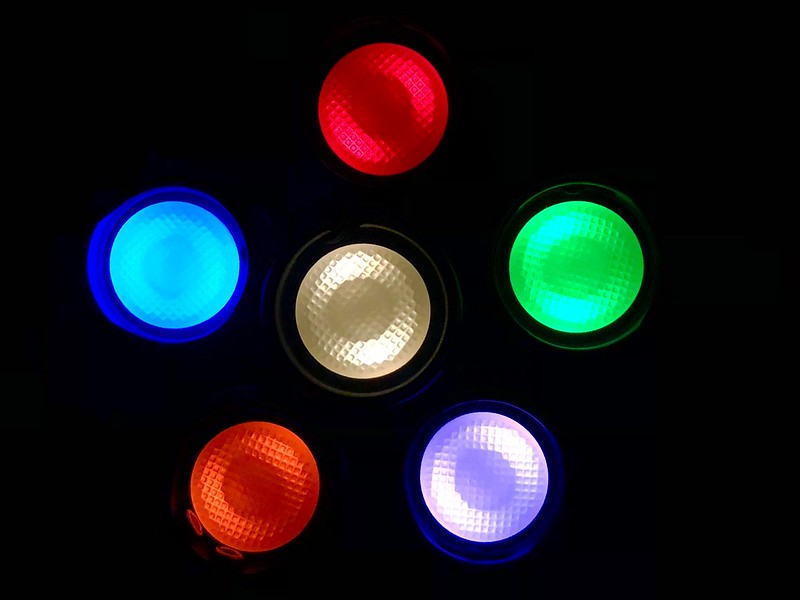
Overall warm white LEDs are good alternative, but not nearly as colorful as the yellow LEDs. Despite the loss in color, the efficiency of the warm white LEDs is worth it to me. 0.99 mA for yellow vs 0.31 mA for warm white is a huge difference - that’s almost a year longer with an NCR18650B battery.
Yellow left, warm white middle, white right:


And finally, I put in a red lighted switch in a Convoy S2+. I think the red looks very nice. It measures 0.46 mA, so a little better than orange at 0.56 mA.
That’s it for now! I feel I went a little overboard with these, but each is unique with different combinations of hosts, LEDs, tints, and beam patterns.
Looking good!
Small update to OP to add links to Led4power and Lexel’s versions before I disappear for another few months ![]()
Thanks PD!
Feel free to update that post with my image that is not on PhotoBucket, but a hosting site that actually works……
It’s a small filesize, so it should fit in the collage nicely.
~D
*edit, second try on the link. This should be direct, as opposed to a resized link
shows “Unrecognized url ”
Teaser:
Hopefully this experiment goes as planned ![]()
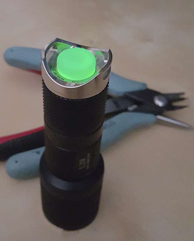
Has anyone completed one of these yet on a Tool AA?
I need to find clear tailcaps to fit one. I don’t have mine in hand yet. Are they 12mm wide? How tall is the button, 5.5 or 7.5mm? It looks like KD did have some 12mm, but maybe not in clear :weary:
KD did stock some green GITD caps, 12mm x 5.5 I believe.
With blue lighted switch.

CRX, do you think there’s enough room to ream the hole out to fit a 14mm tailcap? Would there still be a lip inside?
Could be possible, the internal size is around 16.3mm, the outer space is 15.4mm between the lanyard holes.
Only problem might be the cap squishing out if the retainer is tightened too much

Cool. Perfect details. Thanks CRX!
A while ago I have bought orange tailcaps on aliexpress that fit the Tool AA (they have green and black also):
That is: I bought them for the Tool AA and I assume they fit, but I have not actually checked it since they came in.
Thanks. Yeah, I saw those and a few others. I just can’t seem to find any clear ones in the right size ![]()
Sooo, the bleeder resistor thing plus the tailcap resistor(s) is the path which powers the tailcap leds. For 2x blue leds with 330Ω resistors each, which is 165Ω average, what do you think is a reasonable bleeder resistor? I say this because looks like some of you use a much higher value bleeder resistor than what pilotdog68 suggests in the opening post. This of course is to reduce tailcap leds' current draw but, how much is too much? I think I'll try 2 - 3KΩ at first, hope the tailcap can still be seen reasonably with that. ♪~ ᕕ(ᐛ)ᕗ
Cheers ^:)
It also depends very much on the driver, on some drivers it will never work without messing up the switching timings, but I often use 680 Ohm bleeder and a few thousand Ohm in series with the tail leds, it sounds like your 330Ohm is very low.
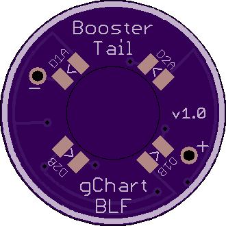
The tail resistors also depends on if you’re using a ring-style board or the older style with the LEDs mounted on the switch board. Based on your 2 LEDs and each with a resistor, I’m guessing it’s the switch board style. Even still, that resistance sounds low. For a 2 channel blue ring board, I would usually use ~14,000 ohm resistors. Not sure about the older style.
My go-to bleeder is a 750 Ohm on nanjg105c drivers. For drivers using an OTC, it really varies as djozz said. I’ve used 220 and I’ve used 1200 (and still not had great results with some!)
Mmm, for an H1-A I will have to try and see what happens:

I think it should work no problem, but of course I cannot say for sure. :-D
Is OTC = On Time Capacitor? The H1-A memorizes used mode after ≈2S, but as far as I can see in the above diagram the bleeder resistor shouldn't mess with this stuff. Am I right if I say C14 and C13 are the MCU power timing capacitors? (^̮^) Well, of course I have not analyzed how it really behaves but looks like that.
Cheers ^:)