I just tried making the driver have one mode only - 1/255 and 255/255 - but it still won't start on NiMH's :-(
Sure - here goes:

I just tried making the driver have one mode only - 1/255 and 255/255 - but it still won't start on NiMH's :-(
Sure - here goes:
You should try the highest mode (255/255). This way there is a constant current draw from the LED and the boost circuitry should not be impaired by the output PWM.
If you used the fuse settings I posted yesterday, the chip is clocked at 4.8MHz. With phase corrected PWM this should result in ~9kHz PWM frequency. This gives me an idea, you could try setting the chip to 1.2MHz (9.6MHz and CKDIV8 fuse set), thereby reducing the PWM frequency. This would result in longer "on" phases, maybe long enough for the boost circuit to stabilize. But for this the driver needs to be recompiled and after flashing the chip might not be accessible any more with your programmer.
I use these parameters when flashing the chip - I took them from your post the other day:
avrdude -P /dev/tty.usbserial-A600aSmp -p t13 -b 19200 -c arduino -u -Uflash:w:BLF-VLD.hex:a -Ueeprom:w:BLF-VLD.eep:a -Ulfuse:w:0x79:m -Uhfuse:w:0xef:mI am willing to try to lower the chip clock - could you give instructions on this ?
Should it fail, and my driver board becomes dead beyond repair - I will just put on a smile, wait for my AK-47/101 drivers to arrive and - most important - not blame you :-)
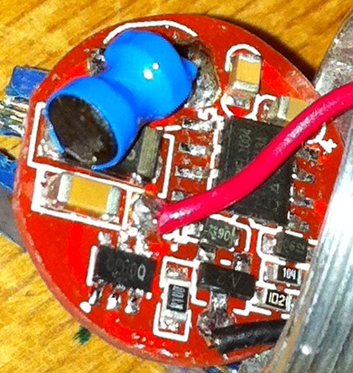
Hmm, the chip below the red wire is a candidate for a boost control circuit, but I can't really tell without knowing how it's connected to the other components.
One thing you could try is flashing the old program into the ATtiny to see if it will work again. This way we can be sure it's a problem with the software and not just a hardware defect. Of course we'll need a copy of the original driver software... sixty545, don't flash your BLF, we need to make a backup of its firmware first!
Well, it's getting late and need to get up early. We should continue with this tomorrow, maybe via IM or IRC.
Yep - I also need to get up early tomorrow - so lets call it the day.
Lets get a copy of the original firmware (from sixty545?) - it could be fun to see, if it will work again.
I guess the original fuse settings are also interesting - perhaps the original clock is set much lower ?
I won't, I have found another victim, my WF502-B with an AK-47 set to 3-level. I can understand that the fixed mode BLF-VLD2 has 3 levels, but which 3 of the 9 defined levels is it? Oh- I see it now, is it no. 3, 6 and 8 (MODE_LVL008, MODE_LVL064 and MODE_LVL255)?
I will do that. A problem is that today is my wedding anniversary, but I guess I can sneak out to dump the firmware if I have precise instructions on how to do it. 
Yes - these are the modes used in the original BLF VLD as far as I know. I had to use some time, to understand how Tido sets up modes - but it is actually quite clever…
I hope Tido can help here, as I am not expert on avrdude and its many options ![]()
sixty545, please try the following command to dump the firmware:
avrdude -pt13 -c usbasp -P com2 -u -Uflash:r:flash-dump.hex:i -Ueeprom:r:eeprom-dump.hex:i -Ulfuse:r:lfuse-dump.hex:i -Uhfuse:r:hfuse-dump.hex:i
This should create four files, one each for the program flash, eeprom, high fuse and low fuse.
OK, I can give it a try tomorrow evening. Then I need a way to pass the files to nkildal.
I just sent you a PM with instructions.
Btw: I just now spent 2 hours resoldering my SOIC clip - it turned out, that 5 of 8 connections had broken.
Some of the pins had pulled back yesterday - I guess I must have broken them in the process of pushing them out again - sigh :-|
I think the 6 pin ic is a PAM 2803 or similar ,DC DC converter which must start first to feed the atmel chip.
To start pin 4 must be in high state as in simples driver without modes.

I took another picture of the driver board, showing the 6-pin chip, but the number on it is not easy to see - it may look like CF80Q...
Is the same as in the C78 and Hugsby P31 , pam 2803, the last letters are year and month,

Two components was obstructing the clip. Had to unsolder them. Not an easy task for them old eyes.
But success!
4 files made:
flash-dump.hex
eeprom-dump.hex
hfuse-dump.hex
lfuse-dump.hex
Hope you can use them, nkildal.
The 6 pin circuit on my driver clearly reads: CFB0Q
! Edited dec.9:
The above dumps cannot be used because the chip prevent reading!
Hi sixty545
Thank you for the files - they have safely arrived.
If anyone is interested in the original files - they can be downloaded from here as a zip file.
I will now try to flash my blf driver board back to the original software and see what happens :-)
Ok - this is weird:
I flashed the chip using sixty545's files - now the light just gives out 2 bright flashes when i turn it on, and then is constant on, at what seems like full level.
Here are the results from verifying the chip after flashing it with sixty545's files - perhaps you guys can see something from the fuse settings:
avrdude -P /dev/tty.usbserial-A600aSmp -p t13 -b 19200 -c arduino -v
avrdude: Version 5.8cvs, compiled on Jan 15 2010 at 17:27:01
Copyright (c) 2000-2005 Brian Dean, http://www.bdmicro.com/
Copyright (c) 2007-2009 Joerg Wunsch
System wide configuration file is "/usr/local/CrossPack-AVR-20100115/etc/avrdude.conf"
User configuration file is "/Users/nicolai/.avrduderc"
User configuration file does not exist or is not a regular file, skipping
Using Port : /dev/tty.usbserial-A600aSmp
Using Programmer : arduino
Overriding Baud Rate : 19200
AVR Part : ATtiny13
Chip Erase delay : 4000 us
PAGEL : P00
BS2 : P00
RESET disposition : dedicated
RETRY pulse : SCK
serial program mode : yes
parallel program mode : yes
Timeout : 200
StabDelay : 100
CmdexeDelay : 25
SyncLoops : 32
ByteDelay : 0
PollIndex : 3
PollValue : 0x53
Memory Detail :
Block Poll Page Polled
Memory Type Mode Delay Size Indx Paged Size Size #Pages MinW MaxW ReadBack
----------- ---- ----- ----- ---- ------ ------ ---- ------ ----- ----- ---------
eeprom 65 5 4 0 no 64 4 0 4000 4000 0xff 0xff
flash 65 6 32 0 yes 1024 32 32 4500 4500 0xff 0xff
signature 0 0 0 0 no 3 0 0 0 0 0x00 0x00
lock 0 0 0 0 no 1 0 0 4500 4500 0x00 0x00
calibration 0 0 0 0 no 2 0 0 0 0 0x00 0x00
lfuse 0 0 0 0 no 1 0 0 4500 4500 0x00 0x00
hfuse 0 0 0 0 no 1 0 0 4500 4500 0x00 0x00
Programmer Type : Arduino
Description : Arduino
Hardware Version: 2
Firmware Version: 1.18
Topcard : Unknown
Vtarget : 0.0 V
Varef : 0.0 V
Oscillator : Off
SCK period : 0.1 us
avrdude: please define PAGEL and BS2 signals in the configuration file for part ATtiny13
avrdude: AVR device initialized and ready to accept instructions
Reading | ################################################## | 100% 0.04s
avrdude: Device signature = 0x1e9007
avrdude: safemode: lfuse reads as 79
avrdude: safemode: hfuse reads as EF
avrdude: current erase-rewrite cycle count is 808531511 (if being tracked)
avrdude: safemode: lfuse reads as 79
avrdude: safemode: hfuse reads as EF
avrdude: safemode: Fuses OK
avrdude done. Thank you.
However - no real harm has been done - as I tried flashing back to the BLF-VLD without problems :-)
Edit: I forgot to write, that the light actually turns on with both NiMH and Li-ion with sixty545's files now - even if it first blinks twice and then is constant on...
nkildal, looking at the flash-dump.hex I would say that it is not program code. I will try again when I get the clip to stay put on the uP. It slides off all the time.
OK, it sits.
When I repeatedly dump the flash, every time one or two bytes have changed at random places.
I'm afraid there is some timing issue here.
Every time I also get: avrdude: warning: cannot set sck period (see earlier in the thread).
I removed two components at the ends of the uP. Could they be needed for proper functioning?
I also had problems getting the clip securely positioned on the chip - I ended up cutting a tiny bit of plastic away from one of the corners on the clip.
It is my impression, that reading & writing the chip should be possible regardless of its surrounding components - but perhaps Tido knows more on this subject ?
However - you don't have to mess too much around with this, if it is too tricky and you risk killing your driver board.
Thank you for your effort so far :-)
I tried to dump an AK-47 driver also. The same pattern here (not the same bytes, but almost).
Edited dec.8:
The chip prevents reading.
Hmm - that sounds weird.
I just got hold of another BLF AA-Y4E from a friend of mine, and he has allowed me to try dumping the data from it.
I will try this out tonight and report back my findings :-)