What a strange choice in fan. That type of fan is designed to spin clockwise and pull air towards it’s center. I don’t see how it’s going to blow any hot air out. In order to be effective, the air has to flow into and then out of the light.
Does anyone here see how that fan is going to produce flow through the light?
Maybe it works similar to the FB1 since it uses a similar fan shape.
If this were the case, the MS12 heatsink would have to be divided in the middle of the vent, like this. Cold air goes in the top part and hot air exits the bottom.
It’s possible they got clever and added ducts inside so that the inlets and outlets are a little further apart.
The issue I see with both designs is it sucking in and recirculating hot air from the exhaust vent. You need to space them as far apart as possible.
Anyway, maybe we will get a better look at the cooling system later.
The exhaust side where the sticker is…the intake is the fan side, like the blower on a house furnace, draws in from the side, cold air intake, and blows out the exhaust side across the heat plenum into the ducts.
It does look kinda cheap just stick a small fan inside that host and thinking it will do magic? yea i guess it wont, not with that amount of watts of power the leds together will generate on turbo… Not like small fans like that are meant to withstand hundreds of watts of power but it will be interesting see some review tests see how it will perform.
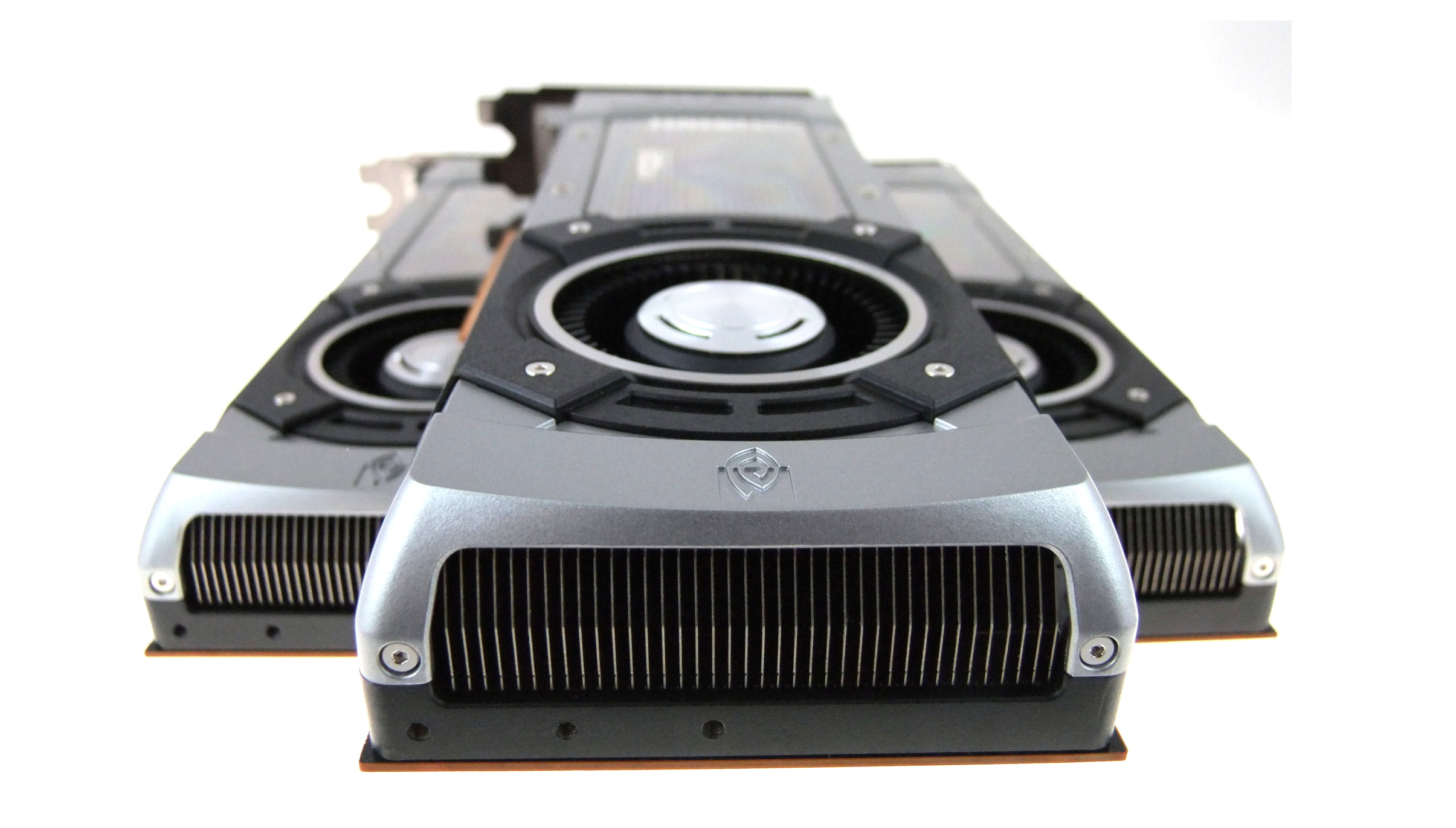
Like compared graphics cards that can get very hot too when playing games, usually its a fan that blows the hot air at the end of card from the heatsink, works usually good.
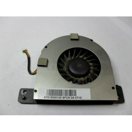
Are you talking about your computer fan picture? I’m pretty sure you got it backwards. The hole in the middle is the intake. You can see the dust build up. It slings the air with centrifugal force out the side. This is how most all laptops work. Intake on the bottom, exhaust out the side.
Going back to the MS12. Regardless of the fan rotation, clockwise or counter clockwise, there is only an intake and no exhaust or only an exhaust and no intake. Do you see my point?
If air is going in, air is also going out. Pretty simple there.
I love the idea, not so much of the 12 XHP-70’s but the fan cooling. They should use that on the 9x XHP-35 and I’d be on the edge of my chair with my hand in the penny jar.
Still, the idea of a massive head with 9 35’s just appeals to me, the stop sign in the middle maybe encourages me to GO!
Store:Shenzhen NuoSenDa Electronics Ltd.
US $836.63 / Set
Discount Price:
US $426.68 / Set –49% 16h:13m:53s
Get our app to see exclusive pricesBulk Price
Interesting, AliExpress is not the cheapest place to buy one huh? lol On the other hand, Lightmalls shows $380 at a discounted price from the $409 suggested retail.
Gonna have to sign up for the group buy just to see how many penny jars gotta go.
No, that’s not how air flow works. If a fan tries to push air in and there is no path for it to exit, air pressure builds up and air stops going in. It’s all about creating a pressure differential.
Think of a laptop. It’s fan pulls cool air in from the bottom and exhausts hot air out the side. Now cover the side exhaust. The air stops flowing and the temperatures start increasing.
In the MS12, I think the air must be flowing like one of the two pictures I drew. I don’t think it’s design is anywhere near as good as the cooling setup we see on the Acebeam X70 which had clear intakes and exhausts.
Seriously Jason, I’m not an idiot. (Well, sometimes I’m not! :laughing: ) When air flow gets backed up it stops going in, doesn’t it? And then of course it’s not going out or it’s building pressure to make something blow. Air going in, air goes out. Really really simple.
I put a computer fan on top of an amplifier heat sink mounted to a 6” disc of 1” thick 6061 aluminum to cool 5 Cree COB’s. At first I mounted the fan pushing air away from the sink, pulling it in from the sides through the fins. Didn’t work well and was noisy. Then I flipped the fan and have it now blowing down into the heat sink, air out through the open sides of the fins… at 60W (3A at 19.1V actual readings at the fixture) the aluminum disc doesn’t even make it to 100ºF, running 12 hours a day.
Computer programming If/Then rules…. IF air is going in, THEN air is going out. Even without an exit point it’s only a matter of time.
Without knowing how they built it, but seeing diagrams showing cool air in on one side and hot air out the other, we are left to assume they actually knew what they were doing. Drawing conclusions without factual evidence is really an exercise in futility…
Some more If/Then… IF you supply enough power to a fan that can sufficiently cool the head for long run times, THEN you’ve drained your battery pack and don’t have long run times anyway.
I have to agree with DB but Jason is also not wrong. It does need a nice path for the airflow. But if air is getting in it is also getting out.
Though, the picture from imalent doesn’t make much sense.
However it does show the power of a big manufacturer, you can just make a custom fan to implement. For my design that uses a fan I have to use a standard type of fan and that limits the possibilities.
I’m trying to understand this picture, but I think it might be BS.
They may have given the picture to an artist and told them to represent cool air going in and hot air going out. So the artist just drew some simple blue and red arrows. I don’t think there’s any way you can get air flowing into the left half of the head and have hot air leaving out the right half as it is seen in the image.
I think the top vertical ports/slots are the intake ports and the bottom port/ slots are exhaust, with a shelf in between, with a large inlet hole in the center or multiple holes in it to create the draw from the outside.
That’s what I was implying though, without some factual input it’s just not possible to decipher what’s going on there. They may have creatively implemented a plastic subdivider for the fan compartment that does indeed shift air across. I know Nitecore has done some amazing plastic dividers in their lights that work but seem to have made their lights overly complicated. Something like that here could, hypothetically, create a pathway for the air movement. Won’t know until we see one I guess.
Are we talking about 360W here? 4416 lumens to 12 emitters, what’s that, 5A x 6V? 30W each x 12? Powered by 8 20700 cells, that’s a heck of a load on cells! And to cool that, we can’t even think about a puny little computer cooling fan pulling tiny current at 12V, no, that’s not gonna get the job done here! We need a serious fan! So yeah, the fan will indeed cut into the battery pack, as if the emitters weren’t already kicking it’s arse!
360W is nothing for 8x20700s. If the cells are rated for 30A, being Sanyo NCR20700A/C, running at 25A, that would mean 3,5Vx25Ax8 cells = 700W max draw pack.
The main problem as you said is power dissipation.
I think they should have just taken a Threadripper sized air cooler with a massive head and a 120mm fan. Would that be overkill? No, not at all. Although I don’t think anybody would like a 1,3kg heatsink/3 pound heatsink, but in this light, that would be liked.
What is the capacity of a high discharge 20700 cell? 3000mAh? You see the problem? If those 8 cells are in 2S4P, which they likely are, you effectively have 4 8.4V batteries at 3000mAh to run the 12 emitters. I can’t see run time being very long at all, and the heat of course would overpower whatever fan they could cram in there. It’s all well and good that a cell can do 10C, but the simple reality is run time is relegated to mere minutes at this kind of discharge rate. Believe me, I know! I actually used 3 pounds of copper for the head of a light, and then some, and with only 3 70.2’s pulling 48.6A from 2 Samsung 30T 21700’s the effect is fairly devastating, both in heat and cell drain. That’s “only” 20,000 lumens…
More less-efficient emitters, more less-effective cells, less heat sink with the addition of a fan, I don’t see it boding well for the monies spent…
Edit: Some might see my comparison as irrelevant, but 12 x 6V emitters run by 8 cells is still 3 6V emitters run by 2 cells, just 4 times in one light. If the heat in my single light with 2 cells and 3 emitters is bad, imagine it multiplied x 4?