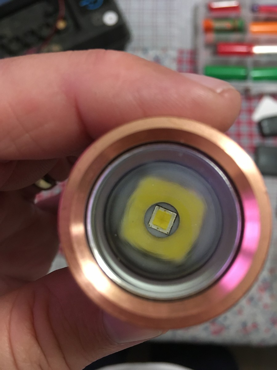
Zozz, the yellow corona comes from the phosphor that is covering the substrate. Since the 70.2 is a flip chip, there are no bond wires to break… use your razor blade and cut along the edge of the die in a straight down chop, like a guillotine, then push that phosphor that’s on the outside off the substrate. If you do this, where only the die has the yellow phosphor, your beam will look very much better.
Just be careful not to chip off the phosphor on the die or it will reveal the blue of the die and put out UV that could be harmful to your eyes. It’s pretty easy though, just be careful and take it easy.
Always have to be considerate of the high power, you SURE don’t want to be looking into something like my Meteor that’s making 17,284 lumens when Turbo is hit!
I’ve gotten used to being hit in the face with lumens, 7600 lumens doesn’t bother me like it used to.
May not be able to see sometime in the not-so-distant future, but hey…
Edit: Hmmm, so it’s said that the XHP-70.2 is like 4 XP-L dies, right? My Emisar D4S is making 7300 lumens with Samsung emitters, pretty intense to be sure. Don’t want to stare into it when it’s, say, in Lightning mode (Anduril), and the MCU decides to throw a few full power bursts… my Meteor either for that matter!
I’ve always heard that the output from a die with damaged phosphor emitted UV light? When MEM was working on the aspheric throwers and the XP-G3 came out, I did some unsuccessful de-doming and had bare XP-G3’s, wired one up in a zoomie just to see what it did. Found it giving me a headache which is the first danger sign of excess UV. Perhaps it was just that die or perhaps it was something else entirely.
It is not the UV that gave you headaches but the 450nm blue light. Eyes are very insensitive to 450nm so with a lot of it you still do not see it very well, while your pupils adjust to the amount that you see and not the optical power and thus are wide open.
And isn’t 450nm blue light UV light? According to research online “The Phosphor white method produces white light in a single LED by combining a short wavelength LED such as blue or UV, and a yellow phosphor coating. The blue or UV photons generated in the LED either travels through the phosphor layer without alteration, or they are converted into yellow photons in the phosphor layer.” Technically UV stops at 400nm, so we’re splitting 50nm of spectrum and counting on the emitter manufacturer to get it right, for the most part.
So it would depend on the particular emitter as to whether or not the base output is in the UV spectrum or merely the blue light spectrum.
Potentially dangerous (or at best hazardous), regardless, so care should be taken to discard a damaged die.
All commonly used white leds in flashlights use 450nm blue leds under the phosfor. They do not emit UV.
Only a handful leds use a 400nm base led (best known are VTC-series Yuji leds) but those are all low or midpower leds so not found in flashlights (except that one or two BLF-weirdo’s made a flashlight out of them).
And recently Nichia used a 420nm base led for the cool Optisolis leds, also midpower and build into a few flashlights by BLF members suffering from tint-OCD.
Nitecore Cx6 (this particular one started out white / red), it now sports a XP-L and a green XP-E2 cause that’s what I had laying around and I like building them as much as using them. I plan to get a PC amber XP-E2 next parts order and replace the green one then.
The color led driver is my last BLF-SK68 board, the white driver is a blf-17ddv3. These are my last two 13A driver builds!
Both run modified versions of TomE’s e-switch13 FW.
First we strip the factory driver and hook to the switch pads, while you’re at it find batt+ and GND on the factory driver contact plate.
Go ahead and sandwich those in there
Do some things here
Pry up the FET’s gate and add a 130ohm resistor cause for some reason the 17dd interfered with the other led on medium and high (but not ml, low or turbo) and started LVP ramp down immediately without it. The gate resistor fixed that!
*correction, lvp ramp was because R2 wasn’t grounded for some dumb reason
Glue is drying in the head, probably be tomorrow before I can wire the emitters up.
I am amazed at all the modding experience going on here. You guys are Good. So much to learn about drivers, I will try to keep up. It sure is tiny for 13A. You sure that may be a World Record tiny high amp setup ? Wow !!
This evening I soldered a loop into one of the triple boards to check current at the emitters, each board is pulling 14.53A for a total of 58.12A, an estimated ~188 Watts. Each Samsung W6 emitter is pushing 1460 lumens for 17,526 lumens at start on 4 Samsung 30Q cells.