Thanks. Yeah, I saw those and a few others. I just can’t seem to find any clear ones in the right size ![]()
Sooo, the bleeder resistor thing plus the tailcap resistor(s) is the path which powers the tailcap leds. For 2x blue leds with 330Ω resistors each, which is 165Ω average, what do you think is a reasonable bleeder resistor? I say this because looks like some of you use a much higher value bleeder resistor than what pilotdog68 suggests in the opening post. This of course is to reduce tailcap leds' current draw but, how much is too much? I think I'll try 2 - 3KΩ at first, hope the tailcap can still be seen reasonably with that. ♪~ ᕕ(ᐛ)ᕗ
Cheers ^:)
It also depends very much on the driver, on some drivers it will never work without messing up the switching timings, but I often use 680 Ohm bleeder and a few thousand Ohm in series with the tail leds, it sounds like your 330Ohm is very low.
The tail resistors also depends on if you’re using a ring-style board or the older style with the LEDs mounted on the switch board. Based on your 2 LEDs and each with a resistor, I’m guessing it’s the switch board style. Even still, that resistance sounds low. For a 2 channel blue ring board, I would usually use ~14,000 ohm resistors. Not sure about the older style.
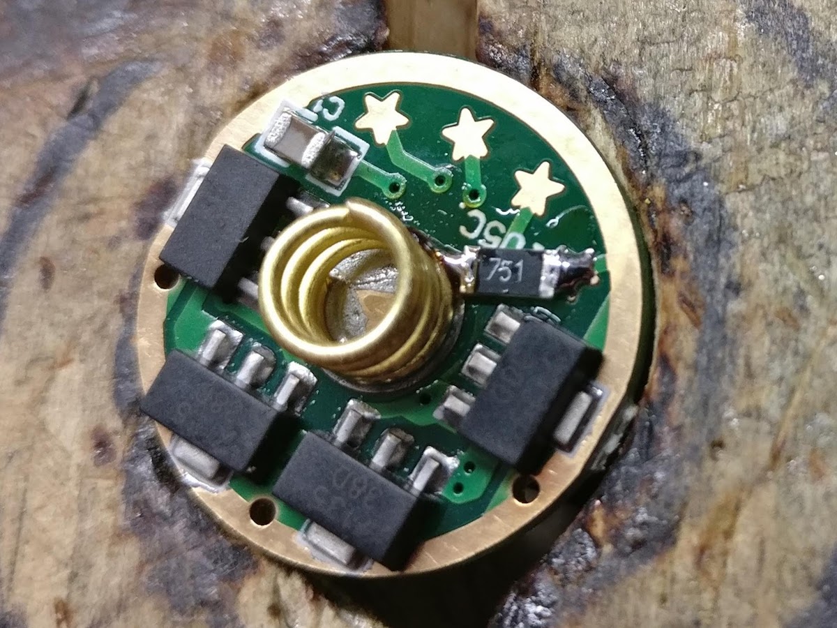
My go-to bleeder is a 750 Ohm on nanjg105c drivers. For drivers using an OTC, it really varies as djozz said. I’ve used 220 and I’ve used 1200 (and still not had great results with some!)
Mmm, for an H1-A I will have to try and see what happens:

I think it should work no problem, but of course I cannot say for sure. :-D
Is OTC = On Time Capacitor? The H1-A memorizes used mode after ≈2S, but as far as I can see in the above diagram the bleeder resistor shouldn't mess with this stuff. Am I right if I say C14 and C13 are the MCU power timing capacitors? (^̮^) Well, of course I have not analyzed how it really behaves but looks like that.
Cheers ^:)
Well, I meant an Off-Time Capacitor like you’d see on the BLF A6 or X6 drivers. For drivers with on-time memory, I’ve had good luck and they haven’t been very picky about the bleeder value. Some of them actually work ok without a bleeder, though very little current can pass thru - a bleeder might help brighten up the tailcap. I’d try something like an 840 Ohm perhaps for an on-time driver. Just my 2 cents… I could be way off base.
Quick tip for bleeders on the nanjg105c-style drivers: I picked up some 1206-sized resistors (from here) and they fit nicely between star1 and the spring. No bridging or stretching needed. And much easier than trying to arrange an 0805 between the 7135 and the spring.
PS - if you haven’t seen them yet, I’ve whipped up some simple constant-brightness tailcaps with LVP built in. Post here.
With a tip of the hat to PD68, who was working with this idea 3 years ago … I built a new “smart” tailcap tonight. More details in this post

Verry cool gchart!
That is very cool gchart, does any light have such a clear voltage readout?
Nicely gone gchart. ![]() Is there a very simple way to explain how it works?
Is there a very simple way to explain how it works?
There’s a bit more detail in the post linked above, but in essence… It uses an MCU to take periodic voltage readings (using internal VREF) and set the 8 LEDs which are on separate I/O channels. It goes to sleep and periodically wakes up to take another reading.
Nice but, as it is, I think it lacks continuity. I mean, the amount of lighted leds versus voltage is way off. Taking a look at some typical cell discharge curves (Batteries & Chargers @ lygte-info.dk) can help with the voltage steps for a better capacity/energy to amount of lighted leds mapping.

P.S.: if the animation somehow gets in the way of practical usage, I'd remove it.
Thanks. You said it perfectly. So its using something I have very little of (a brain) to turn the leds on and off. ![]()
I wouldn’t say that, I’ve seen some of your creations!
I’m really learning this MCU stuff as I go. I have a background in computers/coding, but nothing like microcontrollers. And this is using the new AVR Tiny-1 series which doesn’t have quite as much background or documentation floating around as the older ones (13A, 25, 85, etc)
It appears the learning is coming along nicely. Again well done. ![]()
Give that man (gchart) a Bells! ![]()
That’s really cool. Which tiny-1 MCU are you using? How are you getting it to work? I haven’t really looked into the software toolchain or the hardware adapters for those, other than periodically checking to see if it’s supported yet in Debian… which it isn’t.
Some of BLF’s circuit designers would really like to use it though, and it’s only really being held back by toolchain and firmware support.
Hey TK! Great questions. I’m a Linux guy, but honestly I’ve been using Windows (my first Windows installation for almost 20 years!) with Atmel Studio 7. So far I’ve programmed the 412, 416, and 817. I’ve compiled code for them on Linux, but haven’t flashed using Linux yet. I intend to try that soon.
I think this stuff warrants it’s own thread to help stay focused and drive learning about these chips. I’ll probably start one in the next day or so to share code samples, tips on getting started, and my overall thoughts.
Side note, but I really wish Atmel Studio was available on Linux and Mac. It’s been great having a proper IDE, nice debugging tools, fuse selection dialogs, etc. Up to this point, I’ve just been using Linux text editors to do AVR programming (Viva Pico!)
Really sorry to revive this thread, but is there a 19mm version of the Rev5 bottom board? I'll be using it with the Big Switch top board (forward clicky switch) but my host only takes 19mm tailswitch boards.
Was trying to make my own in Altium Designer but I have no clue what I'm doing lol please help