That finished frame is looking great! :+1:
Nice!
I can see this will look great, especially with the contrasting frame & paper, even when off :+1:
Just had time tonight to catch up on all of the builds. I can’t wait to see this one completed :+1:
I am thoroughly enjoying watching this project. :+1:
I finished up the 3 other panels this afternoon. Here’s a progress shot.
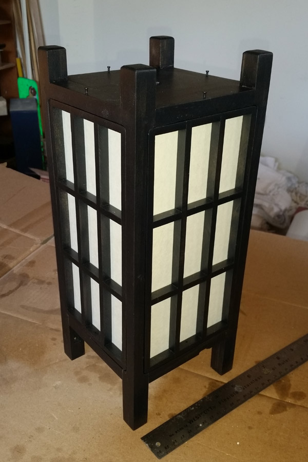
Next the electrics…. But it may be a couple of days before I get there.
With such a beautiful contrast, it already looks lit up. :sunglasses:
So beautiful!
I hope this doesn’t offend but it kinda reminds me of the tardis. Not that that’s a bad thing ![]()
Funny
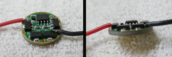
I changed the driver from the original shown It is also a nanjg with 4 x 7135’s but has a custom set of 5 modes. 6, 15, 30, 50 and 100%.
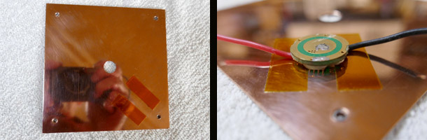
Here is the 4”x 4” upper copper plate that is positioned on the underside of the upper wood plate. The driver is to be cemented to the copper plate. I tried to be careful to solder the wires to the driver flat enough so there was no danger of shorting either wire against the copper plate. To ensure no electrical contact I positioned a couple of pieces of Kaptan tape where the connections were soldered to the driver. Then I used arctic alumina to cement the driver in place.
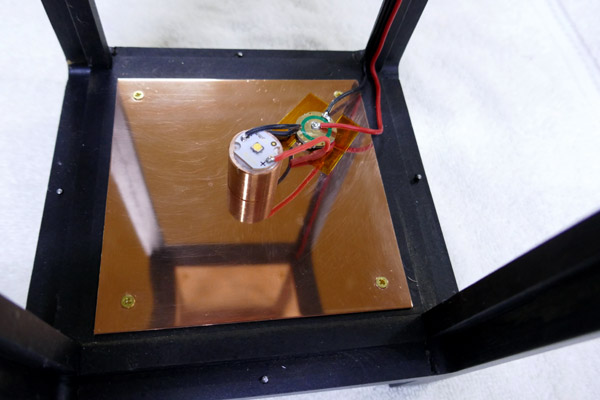
Copper plare screwed to the upper wood plate with brass screws. Led mount and driver installed and wired. The positive and negative wires from the lower section to the upper section run along inside faces of one of the corner stiles. They are fixed in place with small drops of cyanoacrylate.
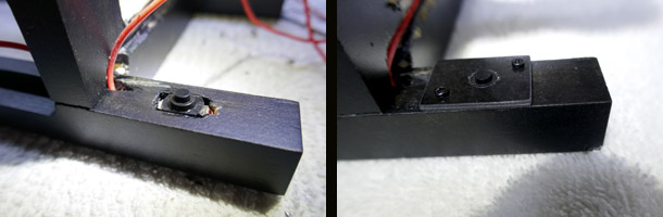
Something happened to the on-off switch between the last test and installation in the stile. It would no longer turn on when pressed. I’m not sure what happened; maybe some cyanoacrylate seeped inside? No real idea. But I had to dig it out of it’s nice neat hole. I wedged the new switch in place with a couple of tiny wood shims. Then I made a cover plate from a 5/64” thick piece of carbon fiber left over from building RC models.
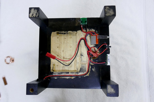
Here’s the view looking straight on to the underside of the bottom wood plate. The USB plug is located at the upper side in the picture. The red/silver board is the TP5000 charger. The charge/full indicator LED is seen to the right. Next down that side is the momentary contact switch to activate the voltmeter and below it is the voltmeter. The various wires are connected and shrink tubed in the 1” diamter drilled recess. The plug is for the battery.
I made a heatsink from a scrap of copper sheet and cemented it to the pad on the TP5000 charger.
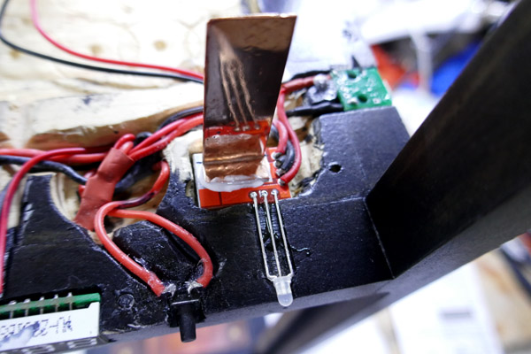
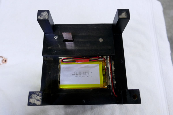
The charger heatsink protrudes through a slot in the bottom cover. There is not a lot of heat; it is only a 1 amp charger. I figure this should ensure the charger will not overheat. There are two cover plates on the bottom. The battery cover is not installed in the next photo. The 3000 mAh LiPo battery is in place.
The next series of images shows the voltmeter read out with the button pressed. Then the indicator led showing red for “charging” and green for “charge completed”.
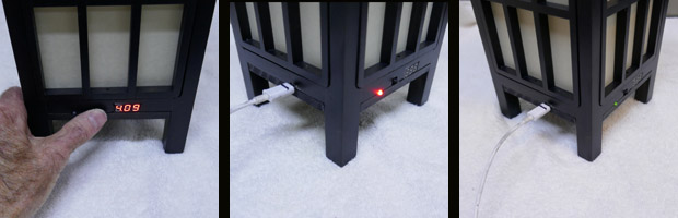
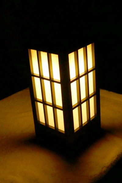
This next image was taken in a darkened room. Yes, it works!!
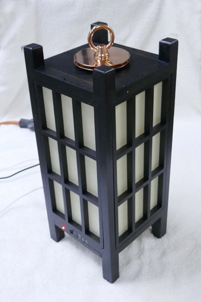
A view of the lantern with copper discs and hanger hoop installed….
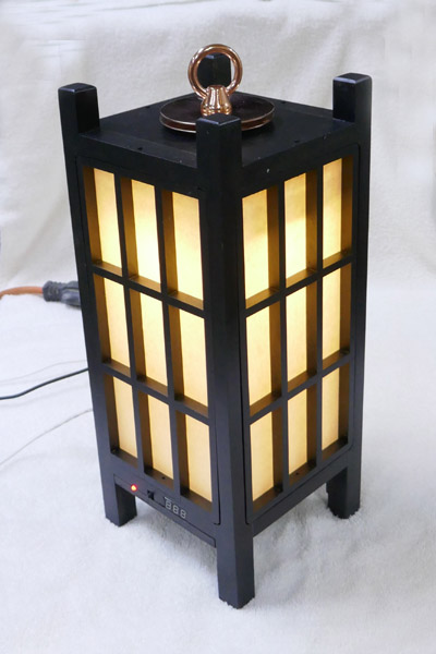
Similar view but with the led illuminated…
I guess my Shoji style lantern is completed. Though I do have some felt pads I need to affix to the bottoms of the 4 corner posts. I did shorten the screen panel retaining nails enough so they protrude just enough to be able to push the nasil pins up a sufficient amount to enable removal.
I plan to re-do some photos as I see dust and dirt here and there. I was rather excited to get it all together and have it work and neglected to clean and polish before shooting and posting images.
Looks pretty awesome from here ![]() Plus onboard voltmeter, very nice
Plus onboard voltmeter, very nice ![]()
It’s beautiful! Nice job! How much you selling those for? Can you have two of them finished for me before Christmas? ![]()
Awsome job, Don :+1:
My bet is on the glue - I’ve ruined a few switches with that stuff :zipper_mouth_face:
Congrats on finishing the build. ![]()
That is a functioning work of art MD. I dip me hat to your skills and abilities to make it all work. Well done. I’ve pmed you my mailing address. ![]()
Looks amazing!
A piece of art! I particularly like the visible mix of classic design and modern technique like the voltmeter.
Knew it would look great either on or off ![]()
![]()
I’m running an operating temperature test this AM. I ran the light on Hi (1.4 amps to the Nichia 219C emitter. The copper pill the l=mcpcb is fixed to settled in at 102F (39 C) with the external copper plates at 85 F (29 C) in a room with an ambient temperature of 70 F (21 C). I also had the charger plugged with the light turned on; the copper fin attached to the charger never warmed to more than a degree or two above room ambient. I removed the bottom cover after the 60-minute test run and the battery was the same temperature as the wood lantern bottom, just a degree above room temperature.
Next will be a runtime test. Later tonight maybe.