When I look down the battery tube past the threads, I see a shiny metal shelf — I assume that’s what the contacts on the head are supposed to reach. Maybe a dab of conductive lube would keep the contacts from wearing out.
An interesting parallel — one design problem of the Arc AAA was that the circuit board was held to the head by a metal collar just crimped tight that eventually loosened up or flaked off due to metal fatigue. Arc covered that under warranty for the owner’s lifetime; I’ve had several fixed over the years.
But ya know, there’s an argument in favor of using a threaded retaining ring to hold the bits in place.
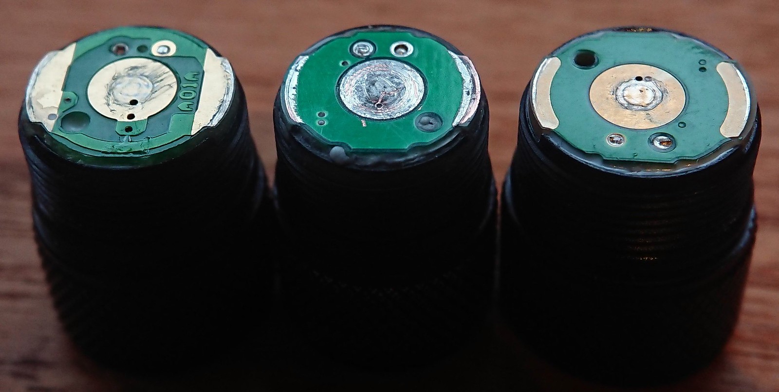
Left my Fenix E01. You can see that the copper is extending to the edge and that the contact area is ok, not great IMO but this light has proven over the years that it is adequate.
Middle is one of the C01 prototypes. I see now that the copper here also does not extend to the side, but that the contact area is only good because the circuitry is not overly well centered on the board, so that one side makes for a very good contact area, the other side much less. Btw, at the time of the prototype I did warn Barry to pay attention to good contact points.
Right is the production C01. The circuitry is even a bit further from the edge of the board compared to the prototype, not much of a contact area leftover.
But it works and maybe for a very long time, again mind that there is no hard data at all at this moment that this is a failure point at all, we are speculating based on what we see. It will not help for this production run but I will confront Barry with this picture.
(in the picture not all boards seem the same size, this is distortion of my phone camera, in reality the boards are all the same size)
Great picture djozz, that clearly illustrates the issue.
I was wondering if there is a simple, cheap alteration to the head design Sofirn could implement in production in order to make the contact areas between PCB and body tube more robust and reliable?
Would just moving the contact pads more outside or enlarging them outwards be enough, or would an alternative design be a better fix (e.g. solder on a thin brass ring on the PCB)?
It would be great if we could come up with a design for the contact areas that would make the C01 as reliable as an HDS, without its complexity or high price tag.
Picture shows a vintage HDS EDC Ultimate 60 (2004-2006).
Thanks for clearing that up, sharing your findings on this potential issue with Sofirn, and providing us with a fix for a potential future problem of the current production C01 :+1:
Maybe press-fitting a thin copper washer down into the battery tube to sit on and enlarge the front-facing “shelf” against which the head has to make contact.
By far the cheapest way to improve this (this is a cheap light) is to make a different driver board with copper extending to the very edge, maybe use one grade thicker copper for infinite lasting contact points.