Yes, R2 was grounded to the ring. So I removed it, wicked off all the solder and found, that the pad of R2 is conected to the ring. There is no way how solve this I guess, look below

Yes, R2 was grounded to the ring. So I removed it, wicked off all the solder and found, that the pad of R2 is conected to the ring. There is no way how solve this I guess, look below
It looks like there is still a layer of solder. Are you using solder wick?
If you can get to the clean pad material you can try taking an exacto knife or similar and break the connection.
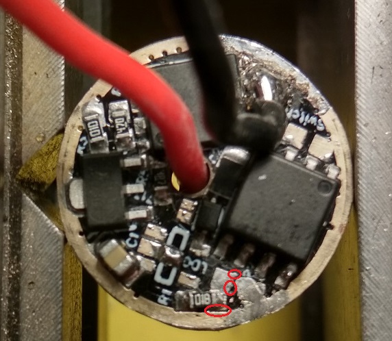
those are possible short areas
also under R2 a short may happen but less likely
Its no problem to make a replacement for a fee that covers shipping parts and the time to make it,
usually cheaper than failure analysis but I try never to scrap a driver that has an error
I test all drivers here befre shipping so I have some that need fix and often points on little design errors (or fab errors because they are not within 6 mil with a layer)
on latest Gen I used 8 or 10 mil safety distance
Okay Lexel, I will check once more the spots you showed as potencial issue, thanks ![]()
Lost a switch pad on my skilhunt driver. Anyone know another option?
You can use one of lexels switch boards from oshpark as a replacement.
Is there another option to connect the switch?
ATiny 13/85 try the #2 Leg of the MCU the other to Grnd.
Awesome. Thank you very much. I know there should be a pin from MCU.
Now I need to figure out were number 2 is.
Thank you and Merry Xmas
Number one marked with a dot on the atmel. Pin 2 is in the same leg line next to it.
Thanks for the save ![]() I been in a rush to get this together before family shows up. Doesn’t pay to hurry, I know.
I been in a rush to get this together before family shows up. Doesn’t pay to hurry, I know.
I guess pin 2 is what Lexel uses on that driver? It can certainly vary. It might be best to trace the circuit back to verify it’s pin 2. (I’ve seen drivers where pin 7 is used)
Alternatively, you can scrape the solder mask off the trace by the pad and attach the wire there. The current is super low for the switch.
What BLF based/designed drivers use pin #7?
Every BLF based driver using the Atiny13/85 I have used, uses #2 Lexels/RMM’s.

Your welcome, Merry Christmas to you and yours! ![]()
The Haikelite MT09R and MT03 drivers that Texas_Ace built uses pin 7. He said he had to flip the MCU around so it fit the design better.
My point was that the pins are assignable, so it’s always good to verify.
Dont understand TA MT03 is different from his basic 46mm SRK he used to use 2 1206 0Ohm, On my designs I traced it without 0Ohm or changing any parts location or orientation
I flipped many drivers MCU from TA designs and never ran into pin assignment problems
I would always stick to the standard firmware pinouts which is compatible between them thanks to some forum members
Some drivers need to run a trace below a resistor
Switch will be aleays pin2
2S pin7 for voltage divider
2 channel pin 5,6
Indicator LED 3
3 channel 5,6,3
Indicator 7
Most everybody knows they are assignable, not BLF based drivers Lexel/RMM (#2 is kind of a standard) that I know of ever used #7, and this IS Lexel’s driver thread, any way good to know it was done on the Hacklites MT09R MT03 for what ever reason?
Right on! :+1:
You know what, there might have been some confusion about the chip orientation. I think it was Pin 2 after all and not 7.