A FET driver, or direct drive, connects the battery directly to the LED. This means the output slopes down as the battery voltage drops.
With a boost driver, the output looks like steps. It gives steady output to a certain voltage or current, then steps down to a lower, but steady output.
They each have their pros and cons.
A FET driver is capable of higher output initially, but then steadily declines. It’s easier and cheaper to build, but requires the right battery and emitter combo.
A boost driver can have a lower, but steady initial output which can be set at the factory. This means less heat and less battery drain. It’s more expensive and complicated to build, though.
You can’t even run an xhp50.2 with a FET driver. It will draw too much power and burn itself up. With a boost driver, such as with Lexels and Richards (MTN E) boost drivers, you can set the current limit for the emitter by changing resistors. Let’s say you want a 3A turbo limit for a xhp50.2. That would probably draw 7A to 8A on the battery. As battery voltage drops, the current will go up (in Lexels and Richards design). Then say at 15A on the battery, the driver will have to step down the output to keep from burning itself up.
This lights are lack of inventory in our factory warehouse and when it is restock we will send the batch to amazon us. We will let you guys know when it is available on amazon and offer a nice price at time time.
I never said my switches had “issues”, I said they were “finicky”.
As it turns out the majority of the “finicky” part was ‘operator error’. . :person_facepalming:
The ‘short clicks’ need to be fast & crisp. The ‘double clicks’ to Turbo must be quick & fast.
Doing it that way my SP33 has been working like a champ!! :+1:
I am beyond pleased with it. . :+1:
I hope at some point they will do one with a ‘ramping mode’.
Mine do not have the ‘Eco mode’ issue Streamer has mentioned.
The SP33 is a great light at a great price as far as I am concerned. :+1:
Yeh, an occasional flaw in products is to be expected. It just sucks when it happens to you. Not to worry though…
The driver flaw in my copy was disappointing for sure, but thanks to Sofirn for handling it so speedily for me. That said, I can’t wait to get another copy of this light when they hit Amazon.
It’s that nice of a light. And I love the size of the 26650 battery tube in hand with this thing. Gotta have another… .
My bad, yes on the SP33. I should have been more clear, I wrongly assumed since we were talking about the SP33 it would be implied. :person_facepalming:
I have edited the my original post & the quote above to indicate I was referring to the when hoping for ramping in a future model of the SP33.
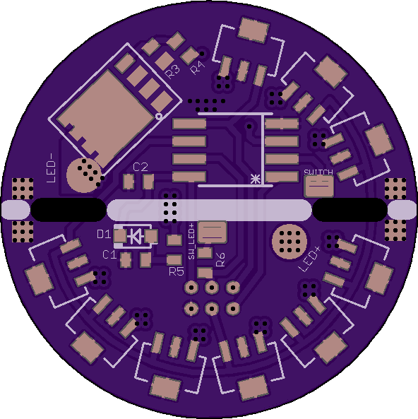
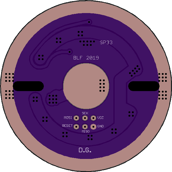
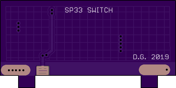
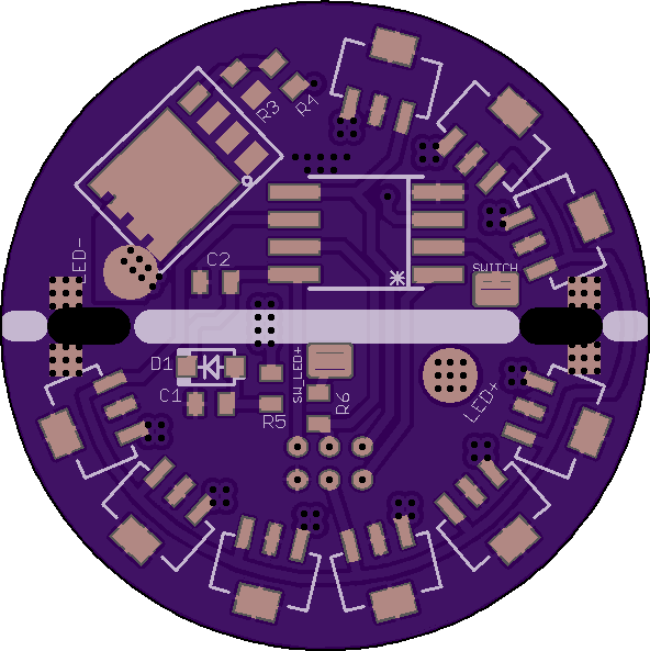
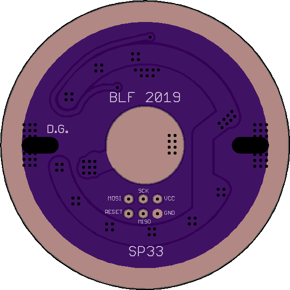
Been making progress on my SP33 driver, still need to make the slots for the switch daughter board to interlock together. Originally I had planned to put components on both main board and the switch daughter board but I was able to fit everything on the main board to allow the use of the factory switch board (with some air wiring). I will be making a directly compatible daughter board (with switch and AUX LED) for a little bit cleaner install (personally I’ll spend the extra ~$6 on ordering it, mainly so I dont have to disassemble the factory driver) but if you want to be thrifty, and you dont mind running 3 short air wires you can save your few bucks and recycle the factory switch board.
Could you give a rundown on what your boards will provide for modders?
I’ve been pondering swapping out the led for a warmer tint. Maybe it’ll be worth it to switch the driver for a different UI and perhaps more output. Is that along the lines of what your boards will provide?
It’s a 1+8x7135+FET driver for running a 3V LED from the single 26650. It’ll allow the use of popular triple-channel FW (ROT66 build). 3 fully PWM’d power channels with indicator LED.
Personally I’ll be running a Luxeon V2 and Anduril in mine!
So before I jump in, the steps to swap out the old for the new are:
Remove the bezel, glass and reflector.
Unsolder the MCPCB and remove screws.
Poke the driver out through one of the holes.
Unsolder the switch wires.
Solder the two new populated boards together.
Reassemble the parts and either use the old MCPCB with a thin layer of thermal paste or get a new one with your choice of tint.
Is that pretty much it? The light is of a size that it looks doable.
Will you sell populated and flashed boards?
Finally, how much? I know I may be jumping the gun but it looks like a very worthy mod to me.
You have 2 choices, either replace the XHP50 with an XM-L2 or SST-40 on the factory mcpcb (those 3 emitters share the same 5050 footprint) or get a 26mm mcpcb for XP LED’s (3535 footprint) to open your options up a bit. MtnE sells a maxtoch 26mm XP mcpcb which is what I’ll use for the luxeon V2.