Seems like it would work when both chargers are pulling about the same amount of current, but what happens when one starts pulling less current. Wouldn't the other be hit with more than 5v?
I quickly glances at a picture of the TP4056 board. It appears that the cell negative connects straight to ground (I could be wrong as I don't have time to study the circuit). If that is the case, couldn't the inputs to the chargers be paralleled to 5v source and then the Batt - trace to ground on the second charger be cut? This would float the output, but the output would be grounded to the positive of the previous cell. So it wouldn't be floating willy nilly.
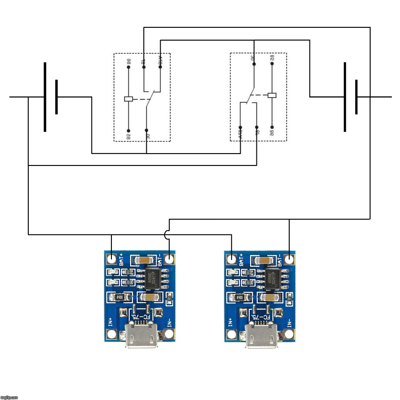
0K, since 5V SPDT power relays are cheap as chips I've cooked up this idea:
Suffice to say the 5V input powers up the relay coils, I just didn't wanted to mess up the drawing any more. This should work… provided that the TP4056 chips behave without bursting into flames with 2S cell voltage on their BAT+ and BAT− terminals while the relay coils are disengaged.
Update, final one I believe. Gonna go the above-mentioned route, though not with bare charging modules like the ones above. I had a spare TP4056 module with battery protection (DW01 + 8205A), and of course I've tested the stuff by attaching 2S cells to its P/B+ and B− terminals. Of course it works right, the DW01 shuts off the circuit when 2S voltage is on the terminals, the TP4056 leds remain off even if power is applied to the board. Removal of the overvoltage condition (relays change cell arrangement) makes it work again. This, Sir, will kill. :-)
Thanks for pointing out these boost charging modules, HKJ. I had not even bothered looking up for that sort of stuff.
The cells I'm gonna use in this setup come protected (built in BMS), and the load won't pull above 1.5A from the 2S battery in any case (no more than 8W into the driver). Should work rather well. Upon 5V PSU connection a momentary short-circuit may happen on the cells (relay coil timing), a no issue since they're protected.
I have the feeling this topic has been beaten to death but still i would like to have your guys opinion.
I also want to charge two lipo’s the cheapest way possible but also do balanced charging.
Looking at all the information online i have come up with the following (cheap) solution trying to use only ONE relay for two batt’s.
Or would the two way relay be better?
Please let me know what you guys think or are there better (small+cheap) solutions
i think this should work…
For anyone reading this and thinks this are tested circuits.
THERE NOT!
If you build them, please do, and let me know if they work
IF i build them i’ll let you know here what my results are….
For anyone reading this.
I have ditched the idea for 2s because i could not find a 2s BMS (CHARGER).
So i’m switching to 3s as there seems to be a good one for that!
Described by this guy:
search on ebay for:
3s PCB BMS Protection Board For 3 Packs 18650
NOTE! you have to see/get the one from he video as it has a proper charger IC on it.
But this is not really balance charging, it’s just individual termination and bypass when one of the cells is fully charged (isn’t it?).
So you have to continue charging until both cells are fully charged.
I think you also need a current limited input.
It’s probably not advised to let the BMS limit the charging current.
That’s only a protection feature, not intended to regulate your charging current.
So, what you would need with this kind of BSM is some boost circuit (5 Volts to 8.5 Volts) with a constant current output.
I guess you could use a LED boost driver for that?
There’s always very little information in those listings…
Oh, another thing, regarding those USB charging boards with protection circuit.
I don’t understand this:
It seems to me that the outputs are mislabeled.
B+ and B- seem to be OUT+ and OUT- in reality.
And so OUT+ and OUT- seem to be B+ and B- in reality.
Because the OUT connections come straight from the TP4056, and usually go straight to the battery (on versions without protection).
And then comes the protection circuit to prevent discharge-over-current and over-discharging based on voltage.
I tried both options (according to the labels and according to my (possibly faulty) logic).
I found that it worked better according to my (possibly faulty) logic.
Unfortunately i can’t remember exactly what the problem was when you go by the labels, but i think i lost some voltage to the cell or it would take much longer to terminate charging.
Because the TP4056 stops charging when it sees 4.2 Volts over the output, but it doesn’t reach 4.2 Volts when there’s that protection circuit in between.
Something like that…
the main problem is that the 2S charge circuits with 5V boost to 2S simply charge the battery
and depend on the balancing BMS board of the battery pack
But then still, it’s only balanced when both cells are fully charged.
You often see this on cordless drills too.
They strongly advise you to charge the battery pack until it’s fully charged.
What does “terminal of the charger using high voltage device” even mean…
If those BMSs don’t shut off power to the battery when charging is completed then the DC DC converter will continuously ‘trickle charge’ the lithium cell at CV which is horrible.
Well i’m ditching the 3s idea also….
It’s just all really confusing.
Anyway i’m probably stick with the PT4065 and a disconnect circuit, not sure on the relais though…
I made a overview of the type of board that are out there.
This is partially guesses so not sure on everything
A BMS shuts off charging power to the battery if overvoltage condition is reached, this won't happen with a DC/DC module with carefully adjusted voltage output.
What do you mean with “trickle charge”?
A DC/DC converter tunes a fixed output voltage, technically this is not trickle charging as it can't overcharge a battery unless a too high output voltage is tuned. Battery voltage cannot raise above output voltage and current flow tapers exponentially to ridiculous levels after a while in CV mode. You're supposed to remove the battery from the charger once charging is finished anyway.
I no offence guys but in the batteryuniversity this is stated:
“The absence of trickle charge further simplifies the charger. ”
In below piece of text
Summary
Charging lithium-ion batteries is simpler than nickel-based systems. The charge circuit is straight forward; voltage and current limitations are easier to accommodate than analyzing complex voltage signatures, which change as the battery ages. The charge process can be intermittent, and Li-ion does not need saturation as is the case with lead acid. This offers a major advantage for renewable energy storage such as a solar panel and wind turbine, which cannot always fully charge the battery. The absence of trickle charge further simplifies the charger. Equalizing charger, as is required with lead acid, is not necessary with Li-ion.
Consumer and most industrial Li-ion chargers charge the battery fully. They do not offer adjustable end-of-charge voltages that would prolong the service life of Li-ion by lowering the end charge voltage and accepting a shorter runtime. Device manufacturers fear that such an option would complicate the charger. Exceptions are electric vehicles and satellites that avoid full charge to achieve long service life.


 Episode 55")