One forum member claimed that "BLF A6 driver unmodded is a bad choice for multi emitter lights the voltage spikes make the MCU reset on turbo"
Can somebody please explain what will cause the "voltage spikes" and what kind of mod is needed in order to prevent it?
Thanks,
Yuval.
A current spike, from off to Turbo always causes a voltage ringing
on newer driver designs R5 4.7Ohm were added and the 10uF cap moved behind it not connected directly to the battery any more
this is knows as a low pass filter, so only low frequency signals can pass, the higher they get the more dynamic resistance they have to pass
additional the MOSFET got on the gate a 47 Ohms resistor to soften the turn on/off switching point
making the time for the current change longer so also the ringing is reduced
Dels measurments of unmodded driver
basically any switching activity causes a voltage ringing, depends on many factors, but basically any conductor has some very very litte capacity and inductivity
I think first discussed here
Thank you Laxel.
Do you maybe know where can I find a schematic of this circuit?
I want to build a driver using thru hole components.

Components list for Texas Avenger Drivers
edited by me a bit to show better MOSFET and AMC choice, 2S components removed
So now to the Drivers themselves, they are designed around the parts list from DEL.
Use 1% resistors all around
R1 : 19.1 k (220 k for e-switch lights, 360k for 2S setups like the L6 driver)
R2 : 4.7 k (47 k for e-switch lights)
R3 : 100 k
R4 : 47 ohm
R5 : 4.7 ohm
BR : Bleeder resistor for lighted tailcaps, varies between 470-630ohm (optional, only if using a lighted tailcap)
C1 : 10 uF (be sure it is rated for the voltage you plan to use, so for a 4S setup, it needs to be 20v or more)
C2 : 0.1 uF (10uf for LDO drivers, can use the same one as the C1)
OTC : 1 uF (functions as e-switch pads for e-switch lights)
U1 : SOIC-8 footprint Attiny25 for bistro, the 20mm+ versions have pads for the Attiny85, the 25 & 45 also fit on them
U2 : LFPAK56 MOSFET (aka, “FET”). PSMN3R0-30YLDX is a popular cheap option, the BSC009NE2LSATMA1 is better but costs more.
D1 : Schottky Diode SOD-323
7135 : Standard 350ma best are “raptor claw” from Micro One company
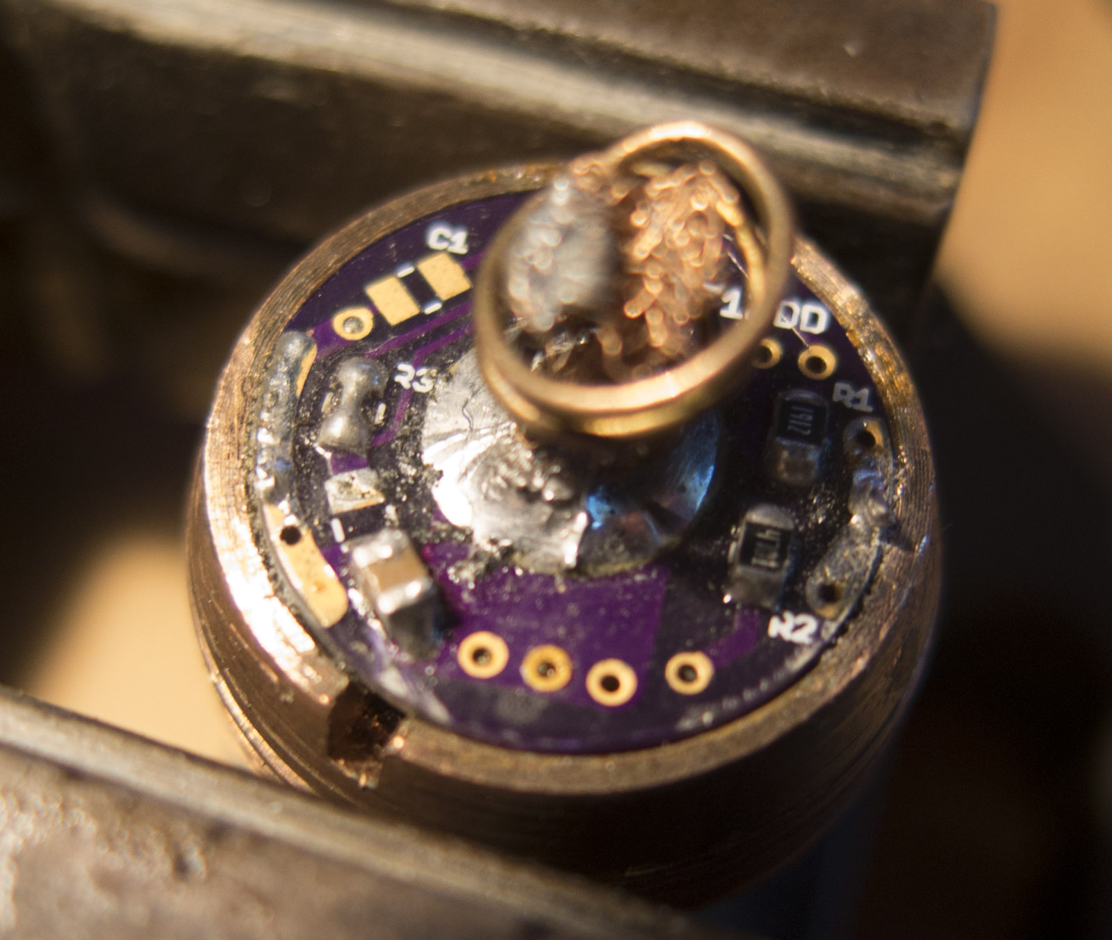
I modded recently a very old design with those components for a guy which light went dark(LED cable was not soldered properly as main issue)
before Mod(also driver rim solder was not sticking whole driver fell off with little force applied
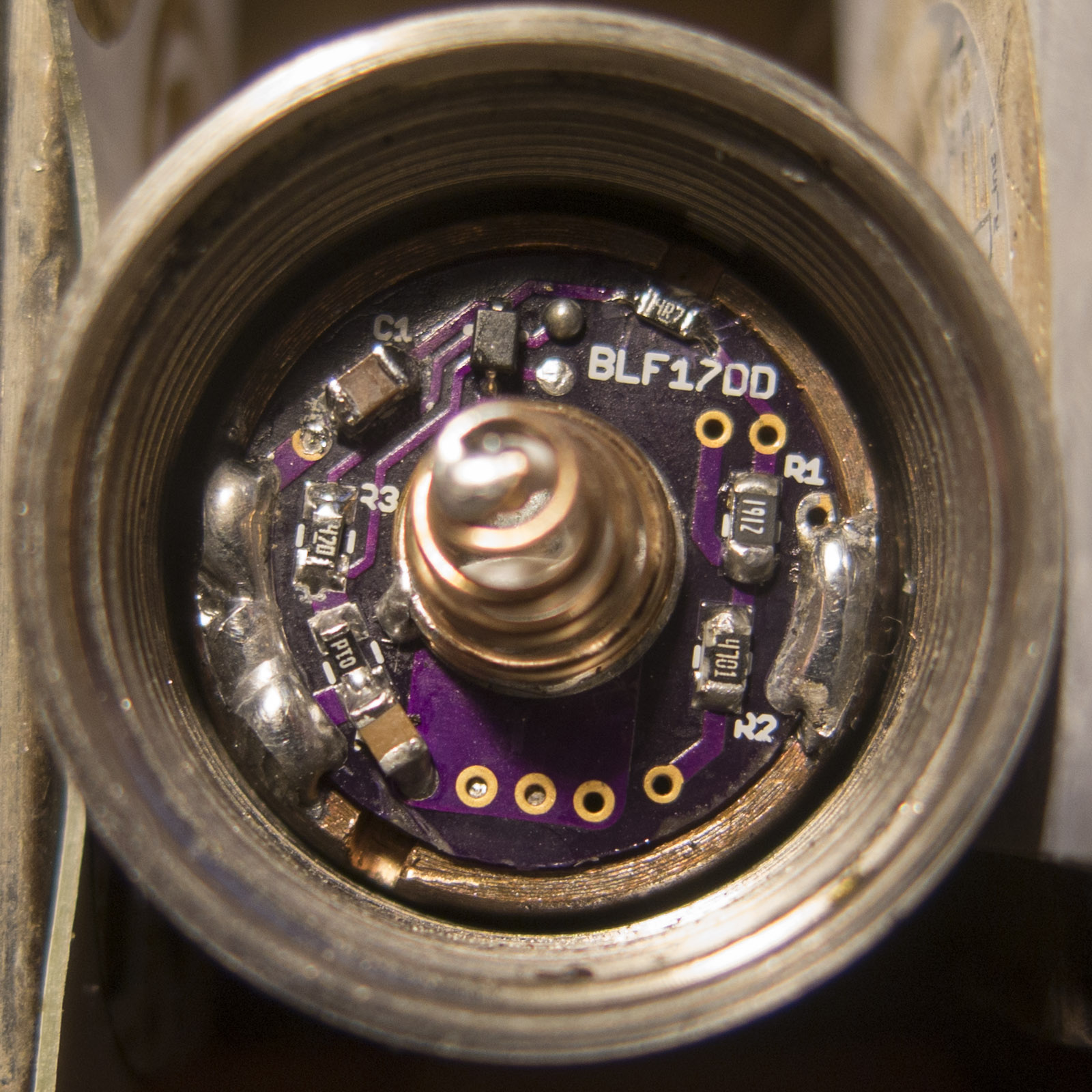
modded with all components
WOW, thank you so much,
I have so many questions but first I have to try to understand it better by myself.
amazing Forum, people helping people!
That’s not it at all.
The A6 driver fails for a very simple reason when going to turbo, if the cell voltage droops too far the MCU re-sets, no more turbo. Since it is directly coupled to the cell, this will happen. And LiIon cells are not perfect voltage sources, they have a frequency response measured in milliseconds (ionic conduction) Solution: better cell, or less ambitious LED array. Or modify the circuit so the MCU has some useful decoupling that might keep it going.
The issue of inductive switching spikes getting back to the MCU is quite different, and affects the more complex MCUs. The Attiny13 is actually pretty robust, but moving forward the more complex ones become more sensitive. Hence the need to put in a very basic, but effective decoupling arrangement (thanks DEL).
The X6/X5 driver is right on the edge, even with only one emitter. Attiny 25 ISTR. Djozz has posted a mod. to improve it. Apparently still in use by Astrolux with only a stacked capacitor bodge, instead of doing it properly.
Further boosted once the OTC was eliminated, and a big holdup cap. added to the MCU, in e-switch applications.
If you look on the Q8 thread DEL posted the schematic for the Q8 FET+1 driver, which is the basis for everything since.
BTW, you don’t need 1% tolerance components, that is just silly (and expensive).
Yes. ![]()
Took me some time to understand the circuit....
If I understand correctly it is basically two different circuits: the power supply circuit and the driving circuit (and the OTC):
Br - bleeding resistor is only used for tail light and can be removed.
R1,R2 - are for voltage measuring for battery status.
R3,R4 - are for driving the FET (only for turbo) eliminating current spikes back to the MCU(?)
R5,C1 - Low pass filter preventing current spikes to the MCU.
C2 - I don't know what it is for.
D1 - reverse polarity protection(?) decrease input voltage at about 0.2v.
D2 - Zener mod to provide 4v to MCU while input voltage is 2s or more? (can be removed if only using 1s)
1*7135 - connected to PWM for moon milk and to reduce power consumption for higher modes.


8*7135 - connected to PWM for modes up to 2.8A.
FET - connected to on/off pin for Turbo only.
THX for the Tip.
Couldn't find it using the forum search do you have link?