I don’t like the xpl2 tint shift
My SP36 has xpl hi 5000k and the beam is very nice
I’d like to try it with SST20
I don’t like the xpl2 tint shift
My SP36 has xpl hi 5000k and the beam is very nice
I’d like to try it with SST20
The attraction of XP-L2 is of course the output in direct drive, this will justify the yellow corona for many especially non-flashoholics, no other 3535 led will get you so much light (although the Samsung LH351D comes close, a 80CRI variant of it would be a good choice also).
My SP36 now houses sliced 4000K 90CRI LH351D leds, makes 3500K in 93CRI and has great tint. But I’m down to under 3000 lumen now so that comes at quite a price. That is why I see 80CRI as a good compromise.
This is killing me... Has anyone taken/posted pics of the driver? Wondering if there's space I could drill in to. I think only 2, maybe 3, have gotten out the driver - any pics, please?
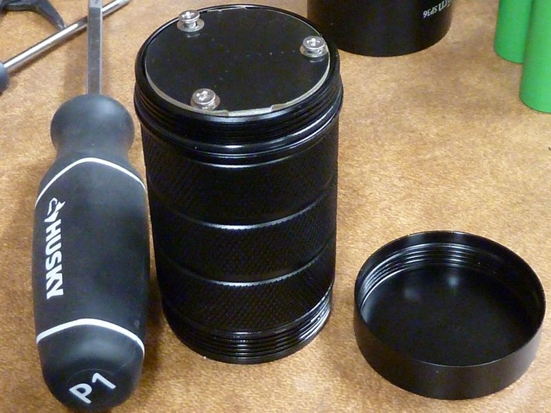
I applied a fair amount of force with a soft handled screwdriver before the wires solder joints gave way, oh boy.
If I destroy the driver, I'd lose the USB charging for a replacement. Will Sofirn be selling drivers like they do for the Q8, some other lights?
That would be another option - simply destroy removing the stock driver, pop in a replacement with no glue -- sounds good to me...
These XP-L2's gotta go, though it would be nice to retain USB charging.
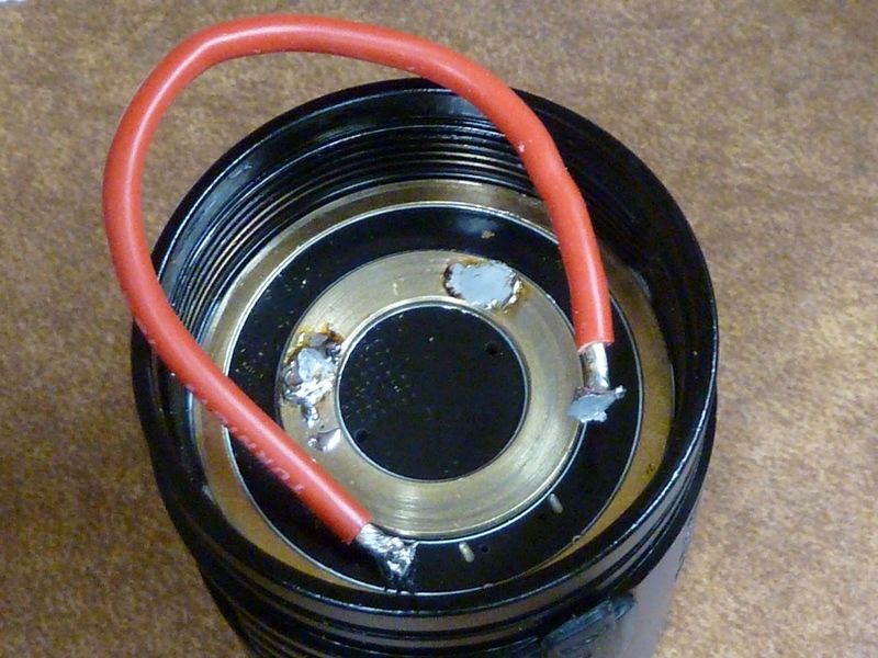
You did try the solder-a-loop-to-the-brass-ring method, right? (see post 62 of this thread, someone else managed the same with a thick copper wire). I had to use my 80W (quality!) solder iron with massive chisel-shape tip to get the heat quick enough into the brass to solder the loop and not unsolder the brass ring. The loop held and the driver glue gave in.
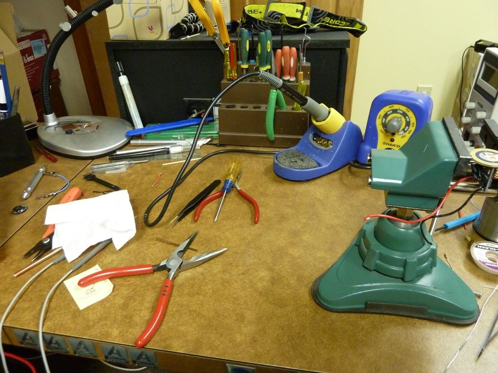
Yes - used 16 AWG wire, nice rubber handled screw driver, this one shown below. No pics, but I soldered the wire little towards the side away form the USB connector, fearing I might damage it when the driver loosens. The solder is what broke, not the wire, nor the brass ring. I had a lot of solder on there, but didn't get a chance yet, but will try again using a big iron tip and more heat. The Hakko FX-888 was set to about 710F, but can go up to 900F.
Hakko FX-888 (prior to the FX-888D model) I use:
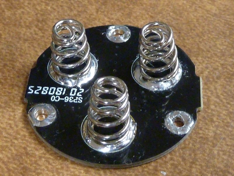
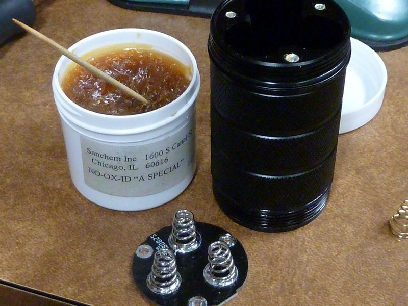
I did swap out the stock dual springs for the large Blue BeCu ones (no bypasses) and measured a slight boost in lumens using the same VTC6 cells. So slight, hard to say whether it was a real boost or not based on typical measuring variables. Only other difference was added solder to the tail PCB on the screw holes where they lay up against the alum battery tube, and added NO-OX-ID on the screw contact surfaces.
The copper strip that I used has a larger contact surface when soldered than a piece of wire, that may be a next step still. But if you have a SP36 copy that by chance has a bit extra glue applied on a cleaner surface you may be unlucky enough to be stuck with an extra tight driver.
This would be good for my liking.
Thanx djozz! Will work on it more, and yep, understood bout the copper strip. Still would appreciate any pics of the driver, top side.
If the brass ring pulls off before the driver and damaged beyond repair, then it's Drill Baby Drill!
Yes, I would buy one like that.
I'm not fond of the ugly beam with tint shift of the XP-L2's. Not sure if there's an optics setup that will make it look better, but I'd much rather see the "good" non-green Samsung 351D's.
And ohhh, did I mention the glue for the driver is a really, really bad idea? Please..... do something better - screws or retaining ring?
I would buy a XPL-Hi version of the SP36
This is with the large BeCu springs installed, extra solder added on screw hole mounts:
NO-OX-ID treatment on contact surfaces:
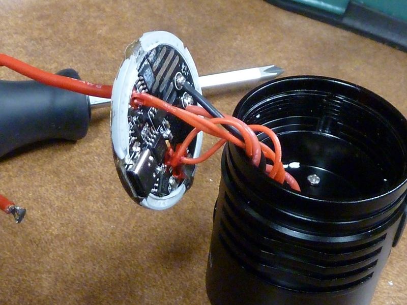
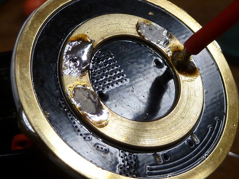
Finally got the driver out, no damage. This is first attempts with solder joint breaking:
Got it off with just one end of the wire soldered, wrapping the wire around the screwdriver and pulling:
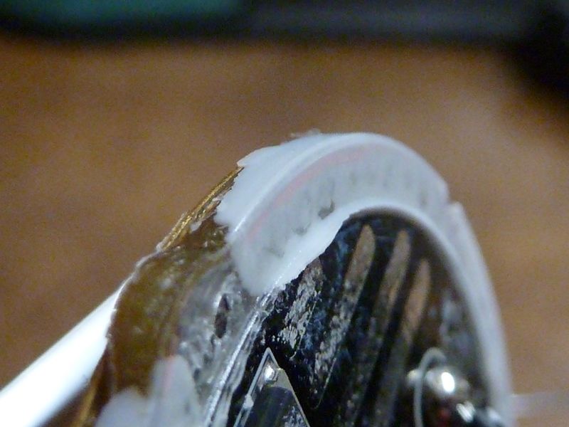
This is a whole lot of adhesive, way too much:
It does seem to soften with heat I noticed, so probably would have been easier pre-heating:
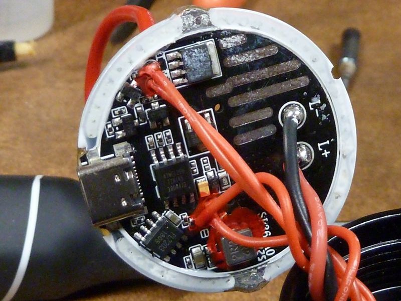
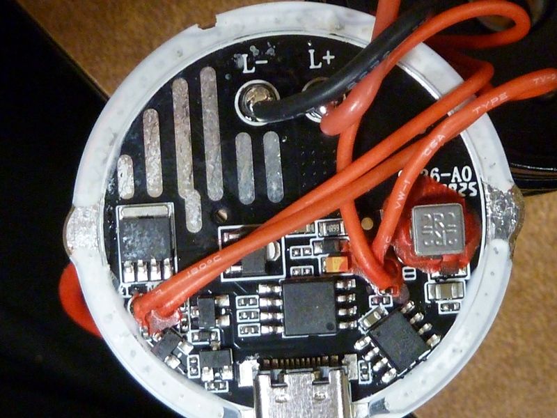
Nice view of the driver. Those stripped traces are a little strange. Looks like the same FET in the Q8. Extra circuitry for the USB-C charging:
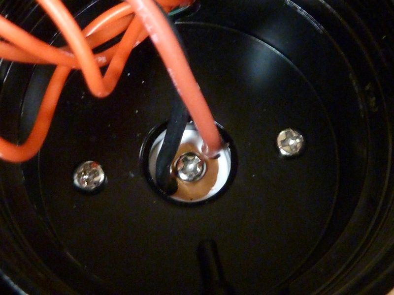
Inside of pill showing the screws:
I would purchase one at or below 5000K. I lean more toward 3500k to 4000k as my favorite but 5000k would be a great start.
Congratulations Tom, that is a whole lot of glue alright!
The driver looks like the neat version of my prototype driver.
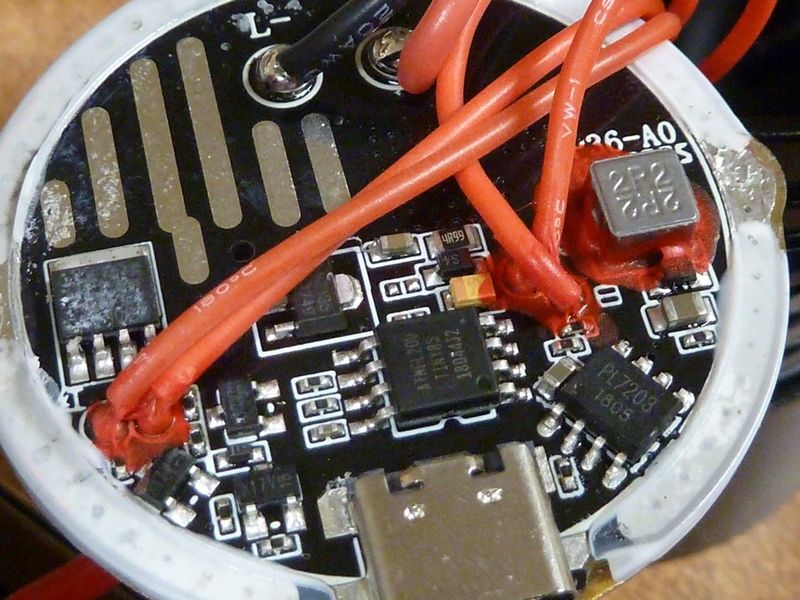
Can someone please give me some hints what this red material (marked with the red arrow) is about, what it is good for and where to buy it for DIY-projects?
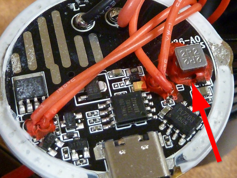
(I don’t know what it is but it looks good) Can I have what he’s having? ![]()
I saw this red stuff (looks like tomato ketchup :-D ) also on the C8F driver. I'm curious about it.
For the thinner wires, I can understand - adds support to remove strain and keep the wires from breaking or strands splitting. Also good for preventing shorts - excellent application because I've seen these small gauge wire solder joints fail before. The red stuff is also used on the back of the switch PCB for the wire solder joints there, btw... It can be a PITA when those short or break.
For that 2P2/2R2 part, maybe electrical isolation (short prevention) or perhaps thermal usage.
I dunno about where to buy, but perhaps later I can get confirmation from an EE on all this. We most likely have stuff like this here at work, but right now our tech position is vacant.