Can anyone tell my horrible memory how the warning lights in the middle work? I spent a good deal of time today running down a 30T with some seriously hot blasts and even running a 4” AC computer fan on it, finally got low enough to start stepping down no matter what level I turned it on at… at this point none of the aux lights worked at all. I pulled the cell and it was at 2.97V. I have another fresh new cell that hasn’t been charged and putting that in the Aux lights work but no middle warning lights. So I put the discharged cell on the charger for a minute or two, got the middle warning lights to show red at about 3.18V. Is this all they do? Red when low?
I turned down the two sets of Auxillary leds around the outside using the POT’s. It was initially so bright I couldn’t leave em on at night as they glowed the room! lol
With the 30T pushing the Samsung emitters, thermal regulation reduces output in about 20 seconds, by then though even at the reduced level it’s difficult to hold onto, especially the head itself, can’t really leave a finger in contact with the finned head area. After repeating this a couple of times the entire light is pretty warm, all the way down to the tail cap. If I double click to high from off, it will run about a minute before reducing, can run it several minutes holding it firmly in hand but yeah, it’s hot. Ambient around 75º.
I’m really pleased with the E07, overall fit and finish is superb as far as the light itself goes, very well done. Just the couple of glitches about that one threaded hole being in the wrong place and the MCPCB being just a little on the large side… address those couple of things and the light is crazy good.
Yea, it’s a pretty small window. I think the one Lexel made for my D4S is 3.1 off, 3.4 red - about the same as M4D M4X shows but I haven’t tested it with a power supply.
From the second picture, it seems that the gap is only caused by the rough edges of the hole. Can’t it be corrected with sand paper to reduce the gap and make the copper and aluminum parts fit better together without extra thermal paste? I have never dismounted any torch, so this really is a naive question.
Absolutely. I admit I am kind of worried about dismounting my two E07 to do that when they arrive, especially as it seems to require some desoldering/resoldering. But in any case, if the situation can be improved to a good metal to metal contact with some sand paper, it might be more efficient than thermal paste, and perhaps less error prone (bad choice of thermal paste, too much paste, not enough, etc.). Your picture was very helpful anyway, thanks. Now looking forward to checking illustrated instructions or videos on how to disassemble and reassemble an E07.
I used a file to reduce the diameter of the MCPCB, flatten the bottom, and cut a bevel on the bottom edge. The MCPCB drops in nicely then and has a tiny bit of play. The screws snug it down and squeeze out any excess thermal paste.
The legs of the optic seat on the MCPCB as well, also applying pressure when the bezel is tightened. Another good reason to have all 4 legs intact. With the leg broken off and a shorter screw applied to that leg hole, the auxillary board is bypassed at that spot… two screws on the other sides of the light hold down both the aux pcb and MCPCB, but on that broken side the shorter screw only holds down the MCPCB leaving the aux pcb to have some lift or tilt.
The threaded holes are not through holes, they have a bottom, so when they found the one hole drilled and threaded in the wrong place they also had to source a shorter screw…. on and on it goes…
Oh and Martin? When the cell is low enough the aux LED’s don’t work at all, neither do the warning LED’s. In standby of course. The light will still function though, so the cell wasn’t THAT low, but the red warning LED’s could not be dialed up to function at all with the cell at 2.97V.
Would have maybe been better to have the warning LED’s in the switch… you could see them then warning you of low Voltage even if the light was on, typically you turn the light off and enter standby you probably won’t notice the warning aux LED’s until you go to pick it up next time to use, maybe then even those have gone out as the cell dropped even lower running the warning lights. Don’t know , but…
The warning lights really don’t mean much to me as I always charge up the cell after I use it. The light steps down to lower modes when the cell is low so if you go that far you already know the cell is nearly depleted.
Oh yeah, the potentiometer’s don’t seem to have much effect at all, a very slight turn can dim the LED’s a step, but that’s about all I can tell… like 2 levels of brightness is all they’ll give no matter how much you turn the POT, stop to stop. I see this both on the purple aux LED’s and the red warning ones.
Wow that’s good to hear. Some people have been asking for compatibility with protected cells. Do you think it is possible? I would love to be able to use the Acebeam 5100mah 20A cell for the 219B version. Seems like the perfect battery for that emitter.
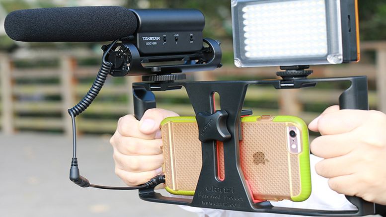
I, uh, think I may have covered the microphone in order to hold the phone in such a way that I could hit start/stop. I’ve heard that complaint before… Tend to talk softly when on the phone or speaking to someone that is close. Sorry. Not about what I’m saying , it’s about the light. lol Guess I could speak like Samurai Jack… (been watching cartoons with my boy…)
I agree. It is encouraging. With the lengthened tube, a large solder blob on the spring won’t dent the cell. I’d hope that the screw issue/broken optic leg will be fixed. Beveling the sharp edges and adding thermal paste should make this a must have for an excellent size-to-power ratio.
If possible and if anyone is listening, I’d like to see switch colors match the aux leds on the head. I’d also like to see the switch lights be able to be turned off, but that may just be pie in the sky dreaming.
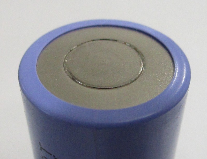
Got my Silver E07 this morning. It came with a crushed 21700 battery. Is it still safe to use this battery? Top is caved in about 50% and bottom has a circular etch which is deep enough to easily catch a finger nail skimming over it.
Also came with the broken leg and screw in the wrong place. My first E07 with the 21700 battery charger that I ordered from ff never came so with nothing to charge the battery with, I used one of my 30Q button tops but it only had 3.8v charge and brightness was nothing special. Charging the 30Q as we speak. Have to say it's a beautiful looking light with the purple leds, nice job ff thank you. I did not notice any problem with the beam either. Seems the broken leg on the optics and the misplaced screw is not doing any damage as far as I can tell.
It's the deepness of the indention at the bottom of the 40T that concerns me most.
I think the deep circle on the bottom of the can is part of the cell. I don’t think that was caused by spring crushing.
My E07 came with 40T installed and both the top and bottom of my cell look much more crushed than yours. And the cell still works perfectly with no problems.
Yes, the clear anodize E07 features extra machining on the heat sink fins so they aren’t sharp.
Basically, Fireflies is seeing feedback and fixing problems in subsequent production runs. I wouldn’t be surprised if in a few months every concern we’re seeing today is fixed.