Linear CC drivers work by burning extra voltage into heat. This happens in MOSFET, which basically works as smart variable high power resistor. So, MOSFET is NOT in fully conductive state all the time like on DD drivers.
Math for power dissipated in FET is simple: Pfet=(Vbatt-Vled)*Iled
Djozz' statement that "FET in linear CC drivers runs hot" is not accurate in general, how hot will FET be depends on three things:
1.Amount of power disspated in FET (equation above),
2.Thermal resistance Rth (C/W) between FET case and flashlight body - this constant tells us how many C degrees will FET get hotter for each Watt of power dissipated in FET(the lower the better)
3.Flashlight temperature.
Math is again relatively simple for steady state conditions: Tfet= Tflashlight + Rth*Pfet
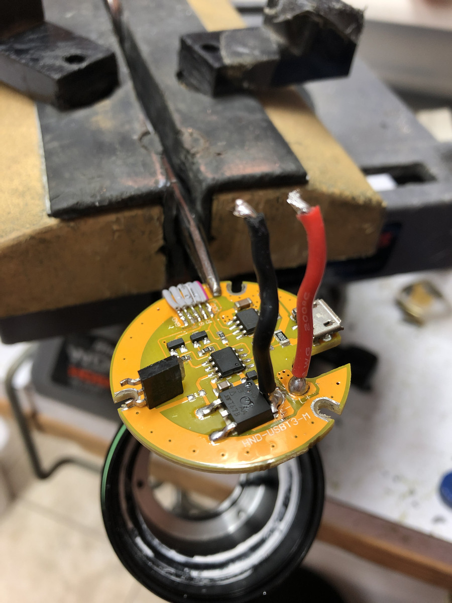
Why move FET to LED pcb?
Answer is Rth.
MOSFET on FR4 PCB has relatively poor value of Rth, I measured about 20C/W for 17mm LD-A4 driver without any thermal "improvements" like adding silicone fillers, so just driver in pill.
This means for each 1Watt of heat in FET, FET would get hotter by 20C. If you take worst case scenario where flashlight is already hot at 60C, to reach 100C FET temperature you need just 2Watts of heat Tfet=60C + 20C/W*2=100C.
That means max. allowed power dissipation should be declared as 2Watts@60C flashlight temp. FET can handle higher temperature, about 150C, but rest of electronic parts (caps,ICs...) which are on same pcb are rated to ~105-125C.
The reason for high Rth value is bad thermal conductivity of FR4 material combined with small cross section and relatively long distance through which heat must travel, and very small contact area between driver GND ring and pill.
Copper layers help a bit, but the main problem is that FET drain pad, which serves as cooling pad, must be isolated from GND ring - no direct copper thermal path is possible.
If you put MOSFET on LED PCB like mosX which has very high thermal conductivity, Rth between FET and flashlight becomes very small,<1C/W!
Thermal conductivity of ceramic dielectric is much higher than FR4 material, thermal path is much shorter(1.5mm), and cross section area is bigger. All this gives much lower thermal resistance.
If we do the same calculation as above for mosX PCB with Rth=1C/W, for 2Watts of heat in FET, FET temperature will be Tfet=60C+1C/W*2=62C! Temp. increase is just 2C, compared to 40C for FET on driver PCB.
I can see why some people intuitively think that it's better for FET to stay on FR4 driver PCB because it's "isolated/protected" from LED heat, but remember that LED PCB/shelf is also a great heat sucker!
As math shows us, FET on driver PCB would get much hotter (and by only its own generated heat), because it's too thermally isolated from flashlight cooling surfaces. Heat builds up as it can't go anywhere efficiently. FET on LED PCB would run much cooler because despite the heat generated by surrounding LEDs, there is still plenty of cooling ability caused by very low thermal resistance of LED PCB/shelf.
For those who still are not sure about all this, one little thought experiment: take two 20mm LED PCBs with any LED and place one on cold (20C) wooden surface, and other on hot (60C) aluminum/metal surface.
Drive LEDs with same current/power, let say 3Watts. What do you think, which LED will get hotter after few minutes?
(LED on MCPCB represent FET/heat generator, wooden surface is FR4 driver pcb, hot metal surface represent LED MCPCB)