I took gChart up on his offer and managed to upgrade my D25 from the original basic 5-levels+hidden modes to a stepless ramping UI.
Thanks to the efforts of gChart, who effectively remapped the original (PIC?) MCU to a similar footprint Attiny MCU (Attiny412), and ported/re-flashed the MCU with TomE/ToyKeeper’s excellent (D4?) RampingIOS see here - the D25 has gone from meh to awesome!
Original UI mode level range, 5-levels from 2.38A to 0.08A (draw at tailcap)
Upgraded RampingIOS range, ramping from 2.38A to 0.01A (draw at tailcap)
In addition to ramping and the exanded level range, the headlamp now has -
Battery Voltage indicator using blinkies,
Thermal Management,
Last-mode-Memory, and
direct access to both Minimum (long-press from Off) and Maximum (double click) from Off.
This is the upgrade this light really needed. Good work gChart :+1:
Note: For the benefit of anyone attempting this, the switch cover plate is “reverse/left-hand threaded” to open. (Thanks to TomE for the reminder)
Nice! Just got in the single LED version ($12 shipped from Ali store here), so could do something with the optics now, least a copper MCPCB I hope.
For the double LED previously modded, I sanded down the scratched end cap so now it's smooth alum - scratches still there but not as noticeable - looks better.
I went out and used my D25 a couple nights ago while I applied crabgrass preventer to my nearly 1 acre. It lit up the yard nicely. And with it being mildly cool out, the temp regulation* helped keep things bright but still in check.
*Stock light does not have temp regulation… It gained that after my MCU swap
Was able to fit a couple of 60deg 17mm Yajiameis in mine. Had to sand down the diameter and base of the optics until they fit. Also swapped in some neutral white XML2s. Can’t remember exact tint but probably 4C.
In preparation of my review of the D25 I noticed something odd about the beam profile. The spot is darker in the center, seems like a slight donuthole.
Could it be that this is the result of the overlay of two emitter beams, causing areas of erasure and amplification?
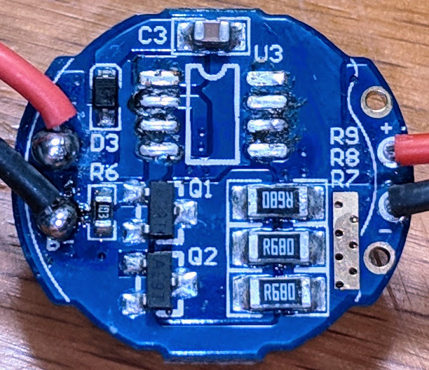
PCB part just under MCU (between MCU and FET Q1) is different as well. It would be nice to check PCD layout on the back side, but it look like divers are a bit different. I would rather expect the same MCU on both. Used FETs and resistors are different probably due to number of leds used, but I think that schematics might be the same for both. Maybe one of those is just an newer revision.