I have used one like it with the XL6009. It’s generally limited to around 4-5 amps (I wouldn’t go over 30-40W depending on the voltage). It’s a general purpose DC-DC buck module and you can set the current limit with the trimmer all it is good for driving led or use it for charging batteries, etc anything needing a CC/CV power source. I used it to run an xhp50.2 6v off a 3S pack. I got 3A at 6.5V before I quit because the thing had no heatsink and the inductors were getting hot. If you have some little heatsinks, stick on the mosfet.
Here’s a pro tip, like pretty much all cheap Chinese electronics, do not hook it up reverse polarity on the input. It will release the magic smoke!
Wow too bad Lightbringer (concerning the Tian Mu grey goo), maybe you should have selected some sort of tracked shipping. I myself do select it way more often now, although I understand the thrill of getting ludicrously cheap stuff.
Yikes! Yes that is ten pieces USB micro-B to type-C adapters for $1.51/$1.60! :-D
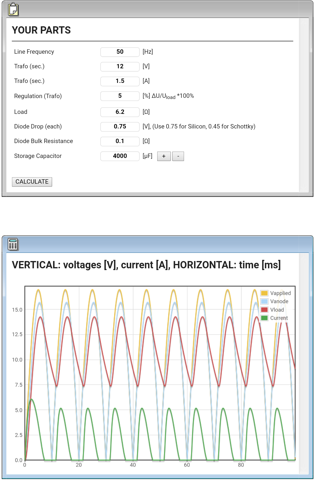
My input power supply will be hand made with an AC transformer plus diode bridge plus capacitors. I plan on allowing up to 1.5A of current to the emitters in series, this is P = V × I = 13V × 1.5A = 19.5W which, at ≈85% converter efficiency, equals ≈23W of power from the supply. According to the following calculator (changpuak.ch):
I have inputted some undershot/overshot figures for safety/reliability reasons. My transformer's actual output voltage is above 13VAC, but I have chosen a 12V figure. Since P = V² / R → R = V² / P = 144V / 23W = ≈6.261Ω load average. Yes I know the module is not a linear load but it should work pretty nicely given the capacitors. I will also use slightly bigger capacitance at the bridge's output, +10% at least.
With all of this I want to make sure the minimum input voltage at the module is always high enough for everything to work correctly, this includes the current regulation logic which at least needs close to 6.5V according to my experience with XL4015 modules.
It made a loud noise tiny firecracker style upon blowing up, scared me LoL!
Heck, there is an electrolytic cap straight at the input. What could I expect protection wise?
Cheers :partying_face:
[/quote
There is no protection aside from that diode near the positive input. I have a 150W boost converter that has a 10 or 15 amp automotive style fuse on the input! I don’t think I’ll kill that one. Overkill? The last victim was a power bank kit and accidentally reversed the polarity. The switch mode power IC started cracking and went up in smoke within seconds. You get what you pay for I guess.
Your quote got messed due to a missing ending square bracket, Sirstinky. ;-)
Diode at the input low side (negative, not positive). I see. If that is so I will remove it and bridge the path since there it reduces efficiency. Then I will reflow it side by side with the output one. This will net me a small increase in overall efficiency. Thanks.
Protection is only needed when there is some risk of clanger somewhere. No clangering, no need for protection hurdles. :-D
Please edit your post and fix it Sirstinky (click ;-) here if you will), add the closing bracket at the end of line 15 where you will find:
<p>Cheers ^:) </p>[/quote
If those schottky diodes are SS34s I'll probably remove them both and install a slightly different package SK54 or SB1040 at the output. Then I could use that SS34 pair to improve the current 2x SS34 + 2x SS24 bridge rectifier I made a year or two ago for testing with the transformer. :-D
Wellp, just for s&g I pulled the trigger on a few of these. Might work nicely for a desk light, if it dials down to 200mA but can also go up to 2A or so.
In my experience with XL4015 CC/CV buck modules they can dial down as much as you want Lightbringer, firefly levels or even lower. It is very important to use logarithmic taper potentiometers for this because we're adjusting perceived brightness out of drive current.
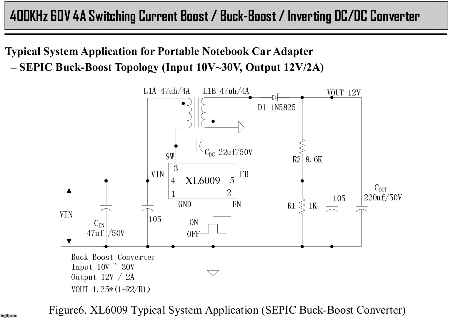
When (if?) you get yours, lemme know if it’s true buck/boost. The 2577, well, I’ve only seen in plain boost config with a single inductor, and you’d need an actual transformer for buck/boost. Or, you end up with negative output from positive input (and both these grounds are in common and imply positive/positive).
And if you look at that .pdf, all the sample circuits have 12V-16V input for 18V output. And the only SEPIC circuits in there use transformers, not plain inductors.
The converter's topology looks like this one found in the manual, so I think it's buck boost no doubt.
By the way, a transformer basically are two coupled coils. An XL6009 can handle its coil pair for it to operate like variable transformer, or so I think.
Unno, maybe they’ve got some trick circuit that lets it be a buck/boost, but…
Like I said, when (if) I get mine, I’ll put it to the test. Would actually be nice if it were a true b-b. Lots lots lots more flexible for the stuff I could do with it.
SEPIC doesn’t require coupling between the coils, although you can often reduce the space taken up by the coils if they are coupled (which increases their effective inductance) and thereby build a smaller conversion module.
See here:
and scroll down to “Using a Transformer”.
As usual with inexpensive Chinese modules, the simplest way to find out is to buy one and see what it does
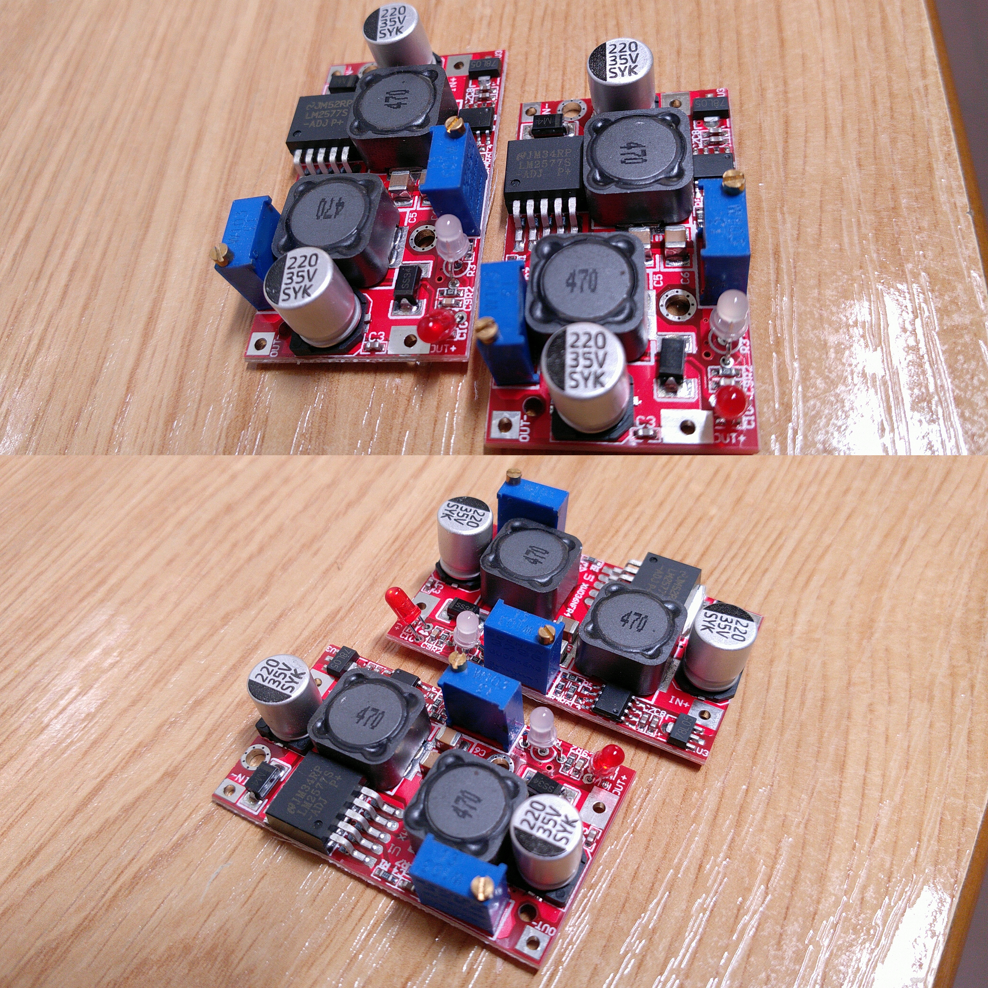
My modules were shipped already. It is a good thing that Correos (main Spanish postal operator by far) reached an agreement with Sinotrans Limited a few years ago, I can choose Ali Saver or Ali Standard and the majority of times this means Sinotrans - Correos which comes home quite fast.
I'll be able to take a quick peek at the modules next week. ;-)
So it matches the title well, it is based on an LM2577-ADJ integrated circuit. The board layout is a little bit different, namely at the switcher's leads for obvious reasons. Whether it is buck boost or not it a mistery is to me until I try it with my PSU, but it should.