The 412 that qchart is using is not QFN package, it’s SOIC with legs.
I usually have a couple of vias in there, and paste does sip through, but I don’t know how helpful it is. I just do it for connection to GND plane.
The 412 that qchart is using is not QFN package, it’s SOIC with legs.
I usually have a couple of vias in there, and paste does sip through, but I don’t know how helpful it is. I just do it for connection to GND plane.
True, but I’ve also been using the 416 and 817 which are both QFN.
Aha, alrighty. Using a hot plate.
I’ve been using stencils for a long time. I got sick of pasting by hand real fast. If I decided to work overtime the same amount of time I save with stencils, the stencils would pay for themselves multiple times over.
This is a great ref source for everything ATtiny: https://en.wikipedia.org/wiki/ATtiny_microcontroller_comparison_chart
You should add this in the OP.
Yeah, I’ve found that to be very helpful. I just added that and a couple other sources as a “Chip Information” section in the OP.
Well… at this point, I’ve ported RampingIOS to run on the Series-1 chips (ATtiny412 / 416 / 817 / etc). That was pretty easy as almost everything was pretty self-contained. And I’ve created a couple drivers from scratch using that setup with good luck.
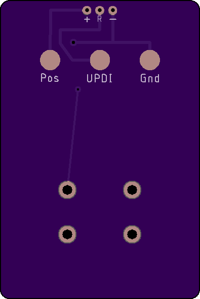
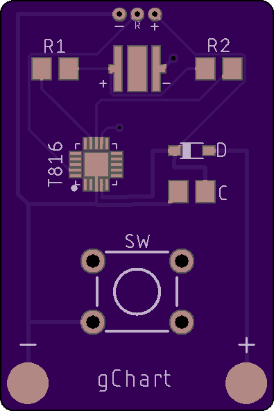
But now it’s time to try and tackle to larger, but more popular options… Andúril/FSM and NarsilM, here we come! I dunno exactly when I’ll get around to porting the code, but I made a development board for the ATtiny816 (or 1616 / 3216). Basically the same at the 817 except it’s 20 pin instead of 24; I don’t plan on need 24 pins anytime soon. Instead of running through regulators or FETs, I’m just using the MCU output to run the LED (limited with resistors). Since this is just for testing, I don’t need it to be bright… actually, bright is bad because I’d just be blinding myself. ![]()
Thanks for the post here. One more thing: Not sharing the new dev boards? ![]()
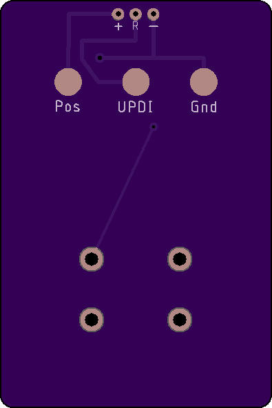
I just noticed I forgot an aux LED. Updating the board in a little bit and will share it then.
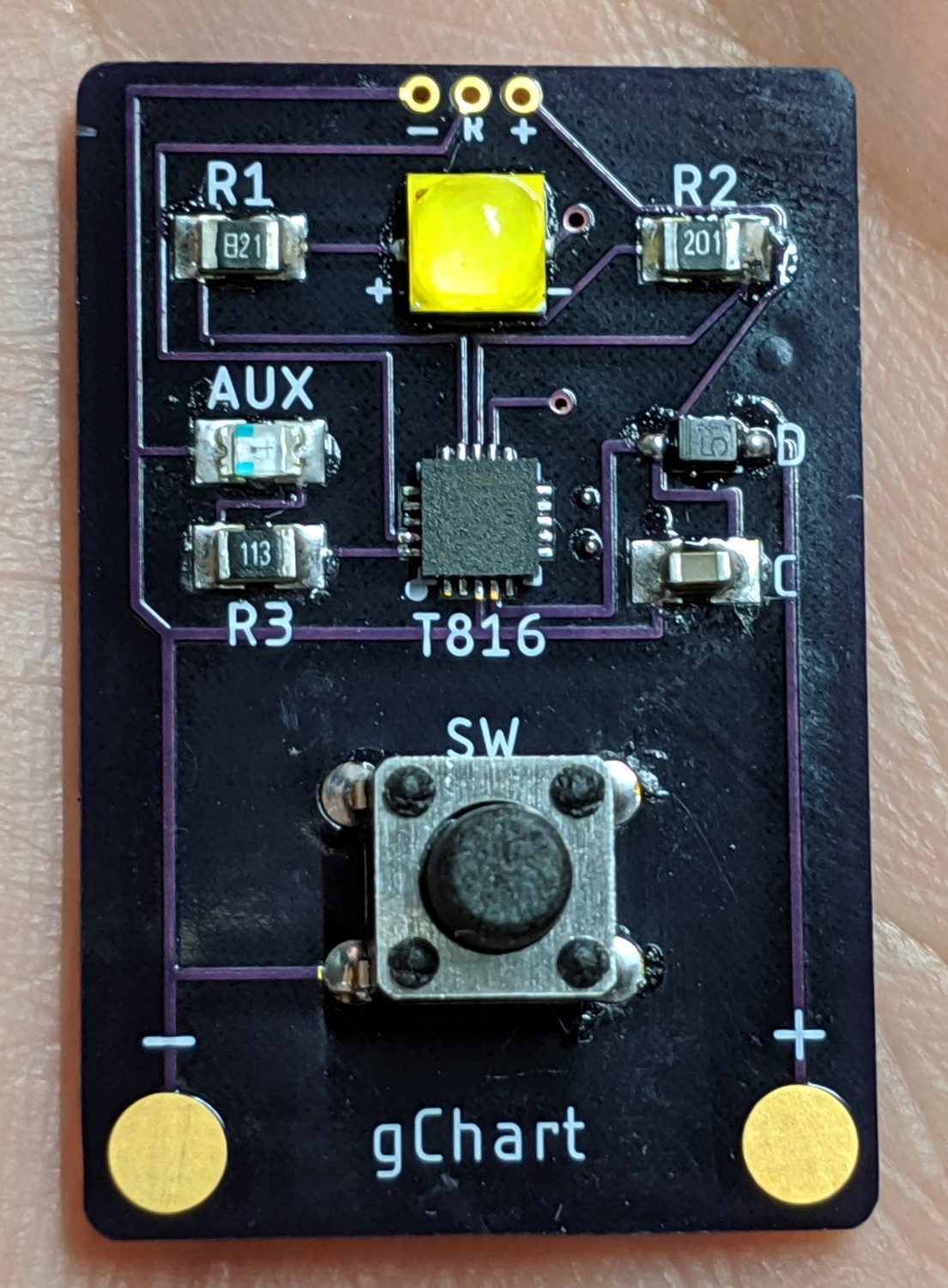
The dev board PCBs arrived today and I made one up tonight. Looks like I’ve got some programming to do!
I think I’ll start with RampingIOS to test out the board (since I already know that works) and will move up to NarsilM and Andúril.
I’ll chime in with a small update… I’ve been working a little with getting all functionality I need running on the 3217 for a specific project. I just got the last piece of the puzzle working, OTSM.
With a 100uF cap measuring off time in 0.125 second intervals with BOD fully enabled at 1.8V threshold I got about 11 seconds with the 1634. With this new 3217 I get about 35 seconds with the same setup. Then I tested using BOD in sampled mode and got just over a minute. In sampled mode it might even be reasonable to test OTSM with a 10uF cap.
Wowsers, that’s impressive!
Sometimes I like reading datasheets for fun and to see what unexplored features are out there. I've been using Timer Counter A every time I needed PWM, but these new 1-Series chips have multiple timers including one called Timer Counter D which is described as such in the datasheet:
The Timer/Counter type D (TCD) is a high performance waveform controller that consists
of an asynchronous counter, a prescaler, compare logic, capture logic, and control logic.
The purpose of the TCD is to control power applications like LED, motor control,
H-bridge and power converters. The TCD contains a counter that can run on a clock which
is asynchronous from the system clock.
In essence, this allows us to use a different clock for the system than what is being used for PWM. Without the TCD, to get high resolution PWM at a high frequency, you'd need to run the system clock at a high speed (like 20 MHz), but that can consume a non-trivial amount of power (10 mA) especially if you want to drive an LED at low power for a long time. By separating the system clock and the one used by PWM, we can use the Ultra-Low Power (ULP) 32 kHz clock for the system while using the 20 MHz clock for PWM only. This can save a decent amount of power (consumption < 1 mA). To prove this out, I used Atmel's ATtiny817 Xplained Mini dev board and set it up for current measurement (removing a single 0-Ohm resistor and forcing current to pass through my DMM as explained in the Xplained Mini User Guide). The DMM used in this test is my Aneng AN8008.
The code for the PWM current tests can be found here. After conducting the current tests, I tested out the TCD functionality for driving the Xplained's on-board LED. That code can be found here.

Note: default 1-Series main clock is 3.33 MHz (20 MHz oscillator with prescaler divisor of 6)
| Clock | Timer | Timer Clock | PWM Freq. | Current | |
|---|---|---|---|---|---|
| Test 1 | 3.33 MHz | none | -- | -- | 1.9 mA |
| Test 2 | 3.33 MHz | TCA, 8 bit | System (3.33 MHz) | 13.02 kHz | 2.0 mA |
| Test 3 | 3.33 MHz | TCA, 10 bit | System (3.33 MHz) | 3.25 kHz | 2.0 mA |
| Test 4 | 3.33 MHz | TCA, 12 bit | System (3.33 MHz) | 814 Hz | 2.0 mA |
| Test 5 | 10 Mhz | none | -- | -- | 5.4 mA |
| Test 6 | 10 Mhz | TCA, 8 bit | System (10 Mhz) | 39.06 kHz | 5.5 mA |
| Test 7 | 10 Mhz | TCA, 10 bit | System (10 Mhz) | 9.77 kHz | 5.5 mA |
| Test 8 | 10 Mhz | TCA, 12 bit | System (10 Mhz) | 2.44 kHz | 5.5 mA |
| Test 9 | 20 Mhz | none | -- | -- | 10.1 mA |
| Test 10 | 20 Mhz | TCA, 8 bit | System (20 Mhz) | 78.13 kHz | 10.6 mA |
| Test 11 | 20 Mhz | TCA, 10 bit | System (20 Mhz) | 19.53 kHz | 10.6 mA |
| Test 12 | 20 Mhz | TCA, 12 bit | System (20 Mhz) | 4.88 kHz | 10.6 mA |
| Test 13 | 32 kHz | none | -- | -- | 21 uA |
| Test 14 | 32 kHz | TCD, 8 bit | 20 MHz | 78.13 kHz | 973 uA |
| Test 15 | 32 kHz | TCD, 10 bit | 20 MHz | 19.53 kHz | 970 uA |
| Test 16 | 32 kHz | TCD, 12 bit | 20 MHz | 4.88 kHz | 967 uA |
| Test 17 | 32 kHz | TCD, 8 bit | 10 Mhz (Prescaler: 2) | 39.06 kHz | 708 uA |
| Test 18 | 32 kHz | TCD, 10 bit | 10 Mhz (Prescaler: 2) | 9.77 kHz | 705 uA |
| Test 19 | 32 kHz | TCD, 12 bit | 10 Mhz (Prescaler: 2) | 2.44 kHz | 704 uA |
| Test 20 | 32 kHz | TCD, 8 bit | 5 Mhz (Prescaler: 4) | 19.53 kHz | 576 uA |
| Test 21 | 32 kHz | TCD, 10 bit | 5 Mhz (Prescaler: 4) | 4.88 kHz | 574 uA |
| Test 22 | 32 kHz | TCD, 12 bit | 5 Mhz (Prescaler: 4) | 1.22 kHz | 574 uA |
| Test 23 | 32 kHz | TCD, 8 bit | 2.5 Mhz (Prescaler: 8) | 9.77 kHz | 508 uA |
| Test 24 | 32 kHz | TCD, 10 bit | 2.5 Mhz (Prescaler: 8) | 2.44 kHz | 507 uA |
| Test 25 | 32 kHz | TCD, 12 bit | 2.5 Mhz (Prescaler: 8) | 610 Hz | 507 uA |
Interesting indeed. I’ve only used TCA and TCB myself, that might change now. Thanks for posting!
Agreed. I never saw the need for it before. But if you want high frequency and reduced consumption, it looks like a good option. I’m going to try and airwire a couple of my ’412 based drivers to get a real driver running with it.
I’ve never tried running the system on the ULP clock, it does look interesting for OTSM. Your test #1 and #13 suggest that I could use pretty low rated caps for OTSM, and with TCD I see no reason to use any other clock for the system. One of these days I have to test how much reliable off time I can get from a 10uF cap at both 3.33MHz and 32kHz ULP.
Well… it only took me a year to get the time to work on this. :person_facepalming: To my defense, I brought home my 5th child (yes, 5) just a couple weeks after getting the PCBs in the mail.
In the past few days, I have managed to (1) flash the dev board using Linux (previously I had only used Atmel Studio for these newer chips) and (2) completely ported over Anduril to run on the AVR 1-Series! I’ve got it running seemingly flawlessly on the dev board. Code can be found here. I’ve tested: ramping/stepped modes, batt check, temp check, flashy modes (candle, lightning, bike, etc), button aux LEDs, etc.
Next up: get this on a proper driver and in a flashlight. This will aid in verifying full thermal regulation, battery warnings, sleep mode current draw, etc.
:partying_face: Thank you gchart! It’s a really important step for our drivers!
This is great news! Nice Job!!
[quote=gchart]
Congratulations mate. My wife would be totally envious. ![]()