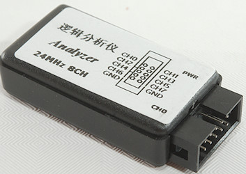
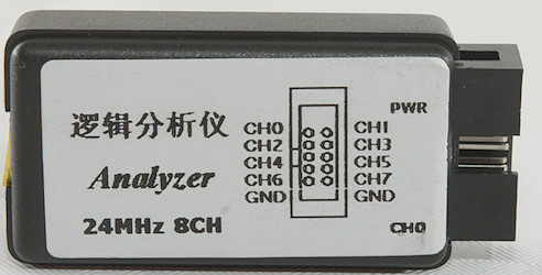
Equipment Logic Analyzer 8 channels 24MHz
Official specifications:
-
Voltage Range: 0V~5.5V
-
24MHz 8 Channel.
-
Logic samples each channel at up to 24M times per second.
-
Logic has 8 inputs — it can monitor 8 different digital signals at once.
-
Fine workmanship and good performance.
-
Easy to use.
-
Long service life.
I got it from Ebay dealer: kk-318
This is a very cheap logic analyzer with 8 channels, it did not include any software and that is a very important part of a logic analyzer.
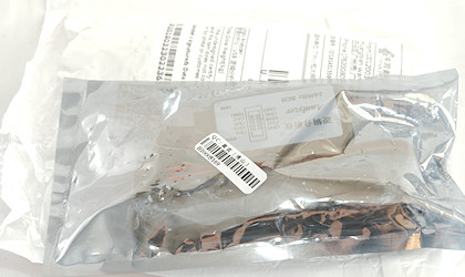
I was in a antistatic plastic bag inside a envelope.
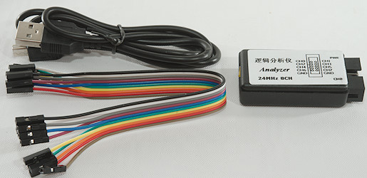
The bag contained the analyzer, a USB-mini cable and 10 test wires (Dupont cables).
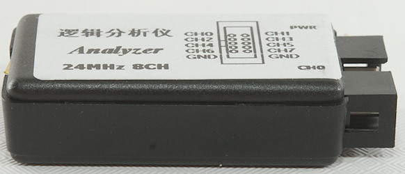
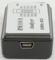

Using a USB-mini is a bit old fashioned, but at least the cable was included. The input is a header with 10 pins that fits dupont cables, two a ground the rest is signal.
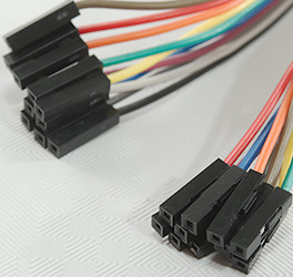
This is standard dupont wire, this means replacement are easy to get and also some with a pin in one end for directly connecting to breadboard.
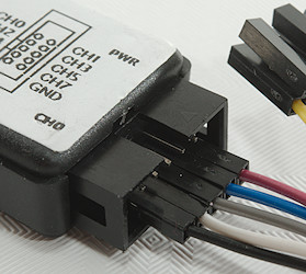
Some input wires connected.
Software
This piece of hardware is fairly standard and the lack of software is not a serious problem, the two possibilities are: Sigrok PulseView and Saleae Logic.
I started with PulseView, there was a bit fun with installing a driver, but it worked. Later I tried Logic, but it could not find the logic analyzer.
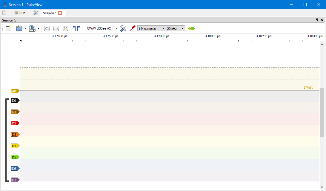
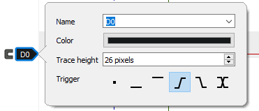
It do not look like a perfect fit, because it also includes a analog channel and that is not present on this logic analyzer, everything else looks fine.
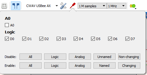
Lets get rid of the analog channel.
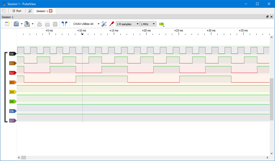
Four outputs from a binary counter.
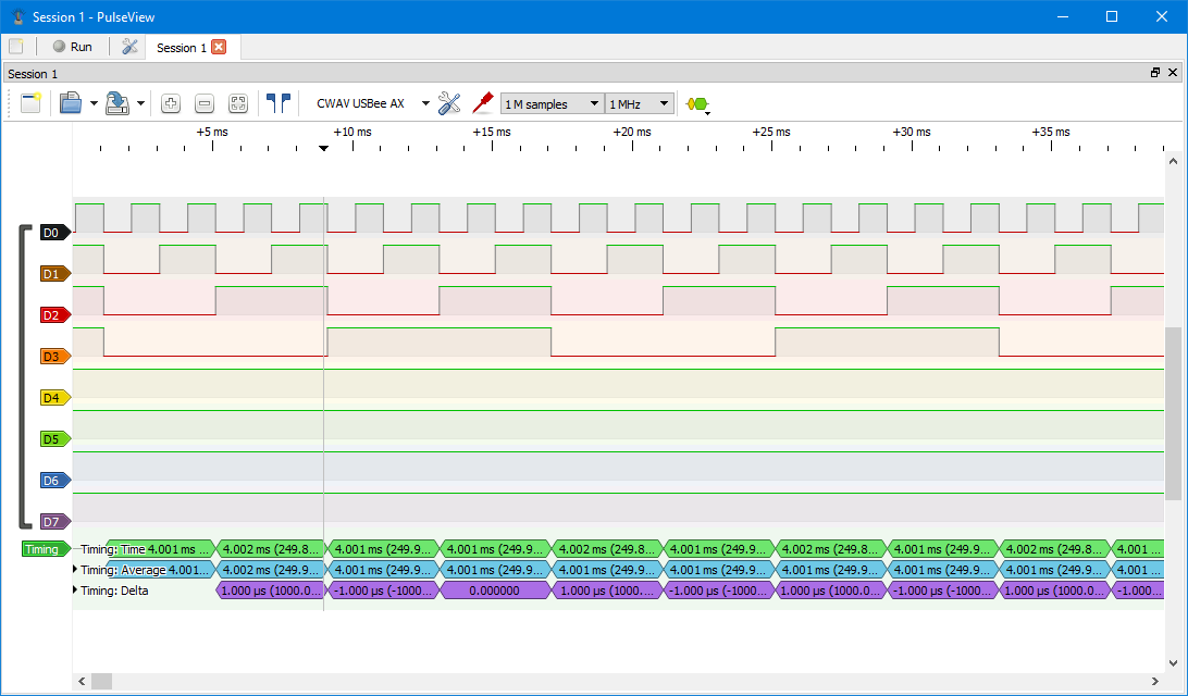
The time scale at top may not be the best ways to check the timing with, but this software has a lot of tools all in the decoder menu. Here I use a “Timing” decoder on D2. The delta time of 1.000us is due to the 1MHz sample rate, the software do not reduce the shown digits to the actual resolution.
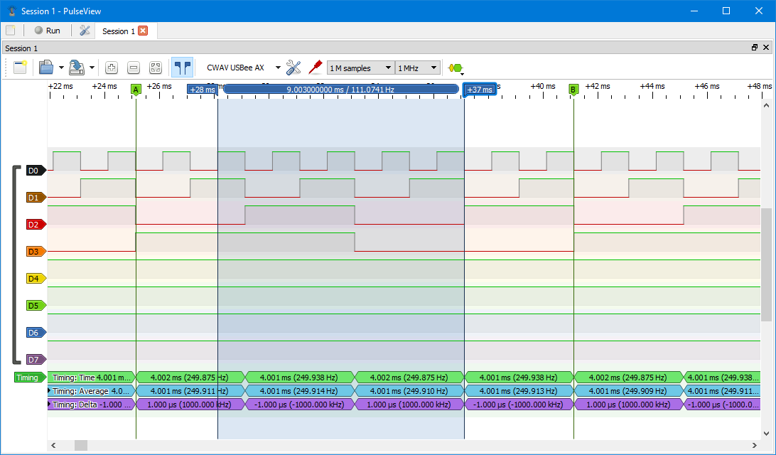
Some other options. The blue area is the cursor and A & B is markers.
The cursor can be used to measure time with, the markers makes it easier to find a specific location on the timeline.
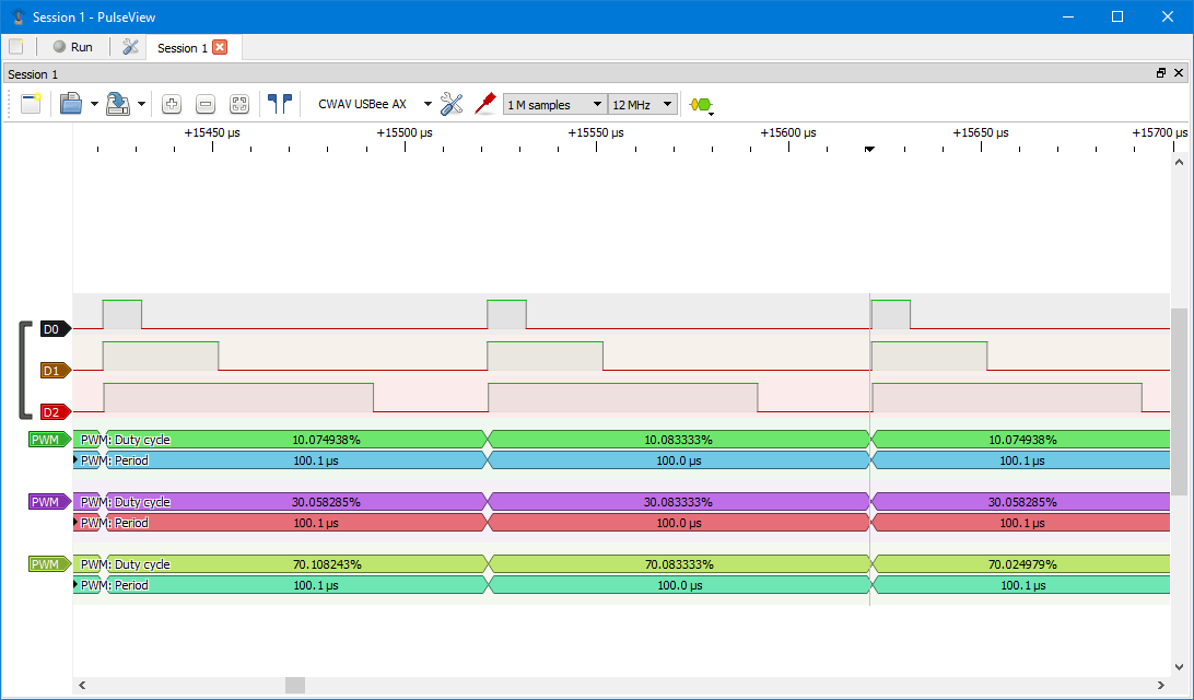
Here I look on a couple of PWM signals and I use 3 PWM decoders at the same time.
Lets use a trigger, this means sampling will not start before this condition is true.
When more channels has a trigger condition they must all be true at the same time.
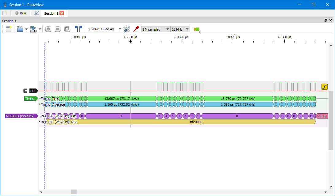
Data for a Neopixel inclusive a timing decoder and a WS2812 decoder. Here I am missing a button to zoom on available data, I had to use the scroll wheel to zoom in on the data.
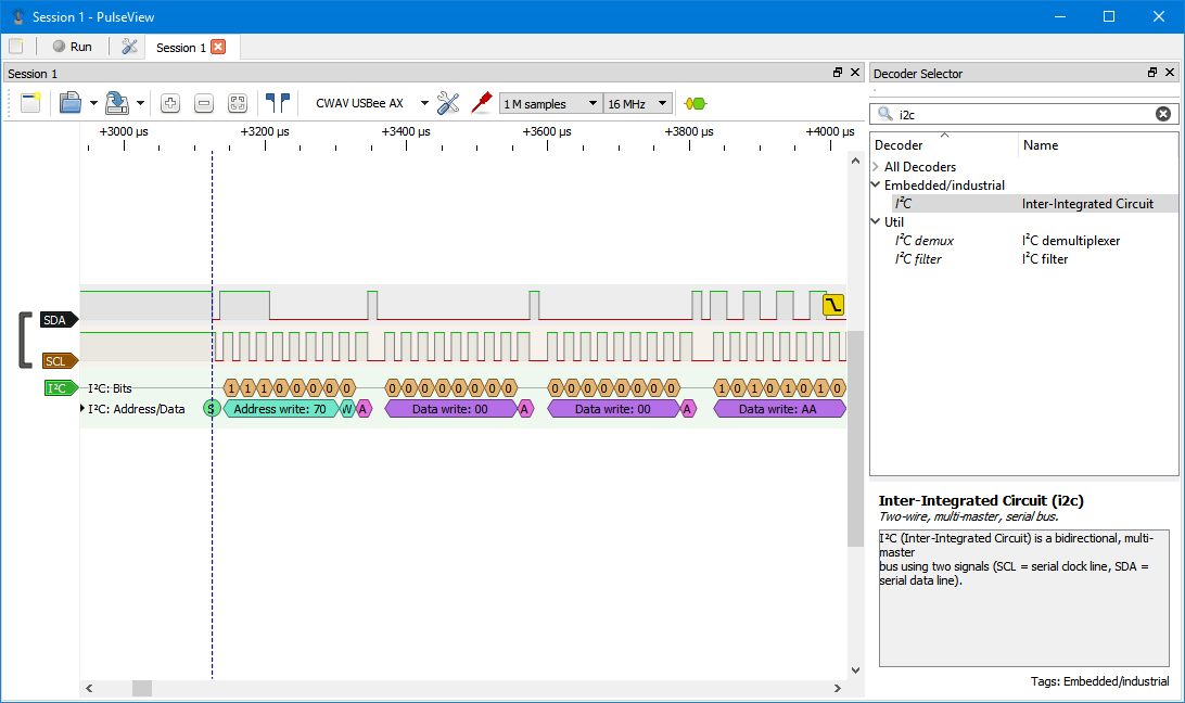
A look at some slow I2C communication where I have named the data lines and is using a I2C decoder. This is a beta version of PulseView where the decoders are grouped.
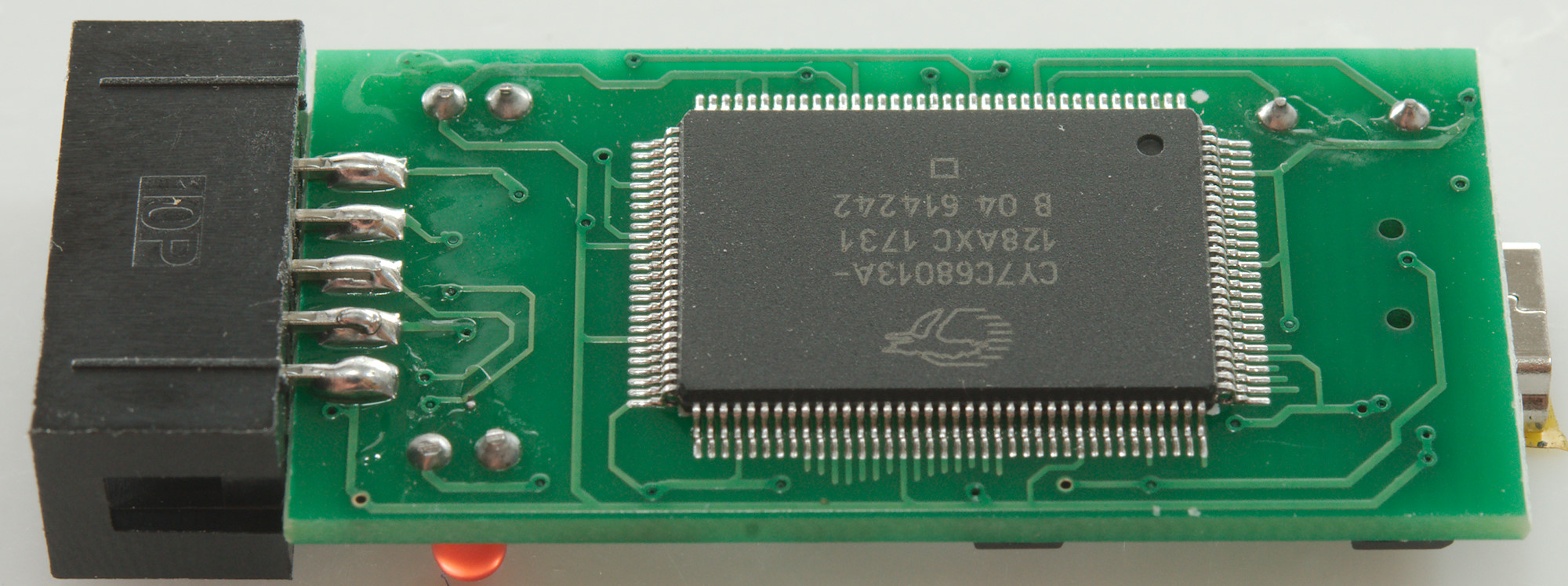
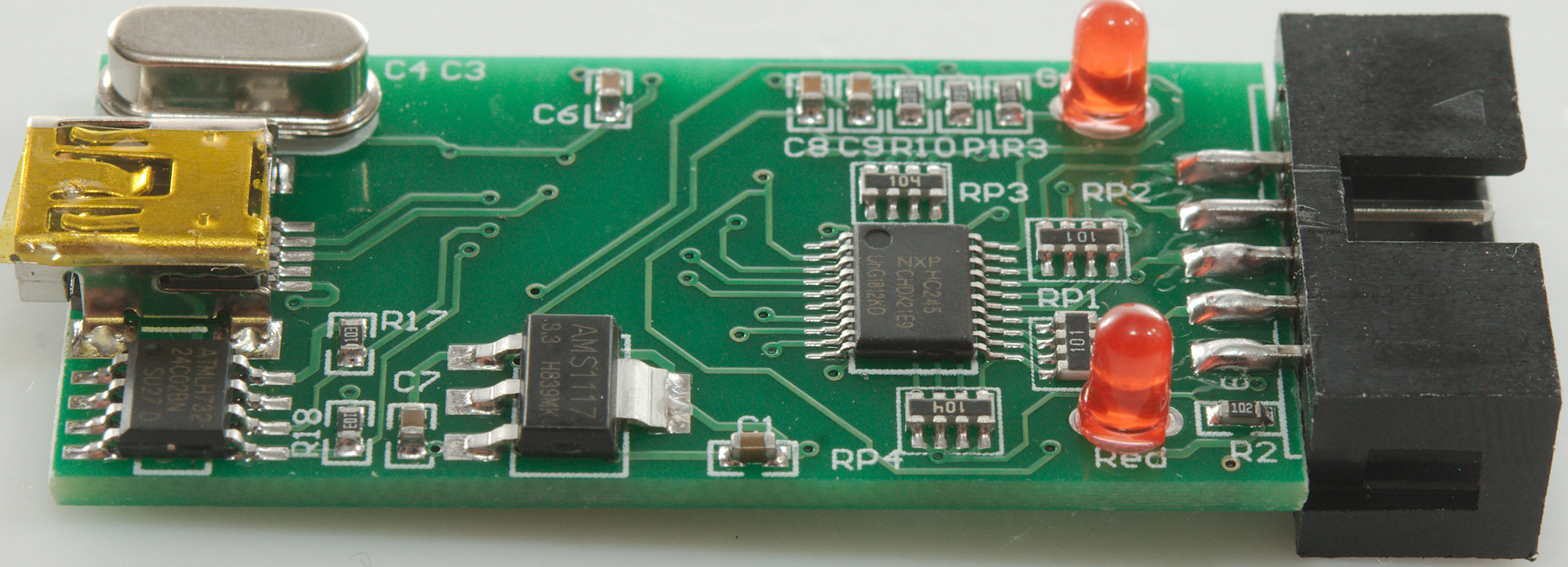
Tear-down

There is no screws, the box is just clipped together and can be pulled apart.
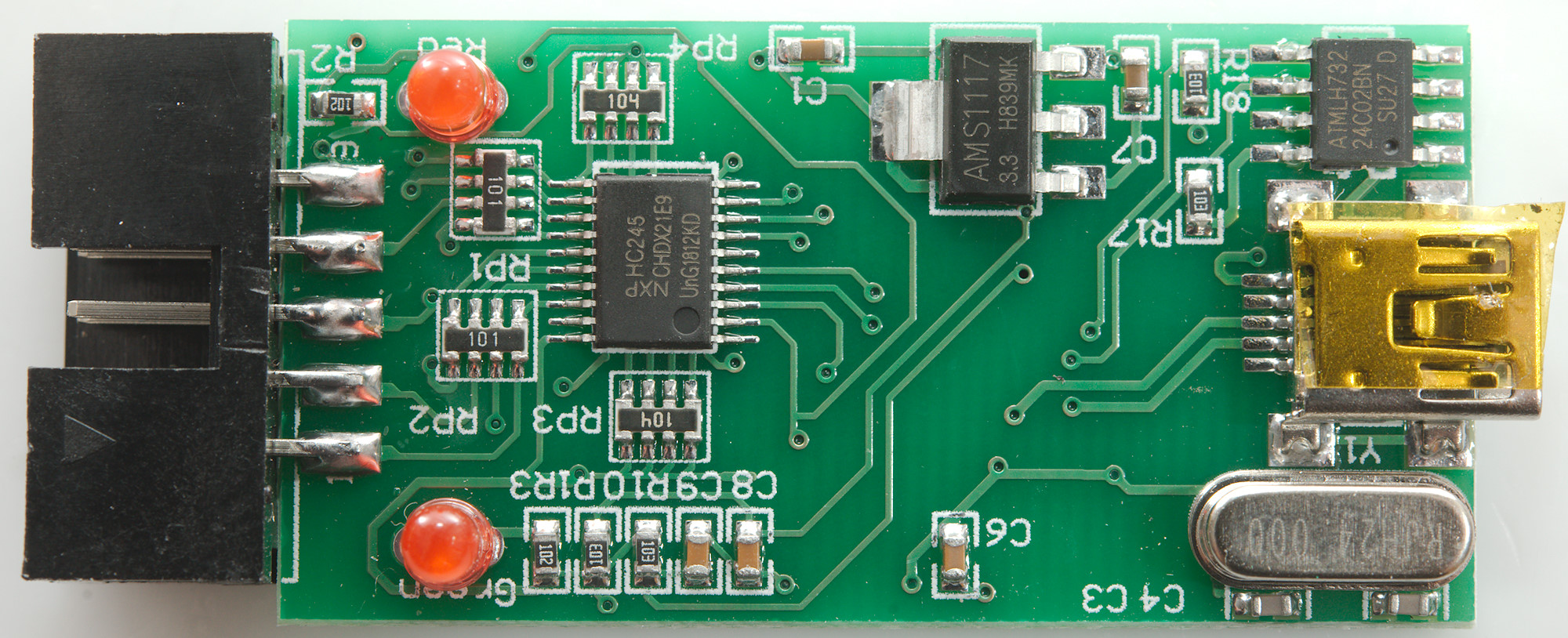
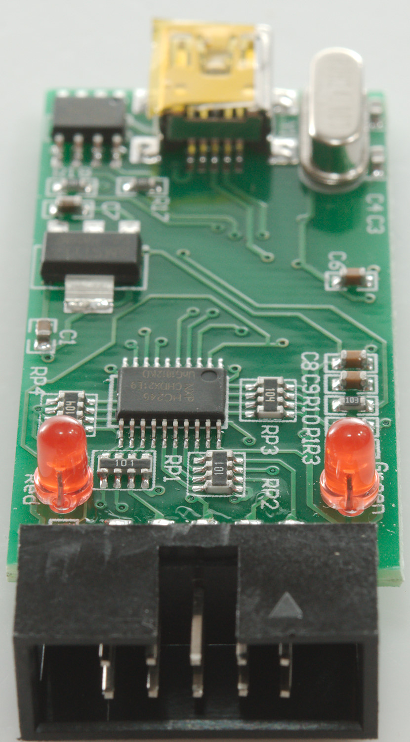
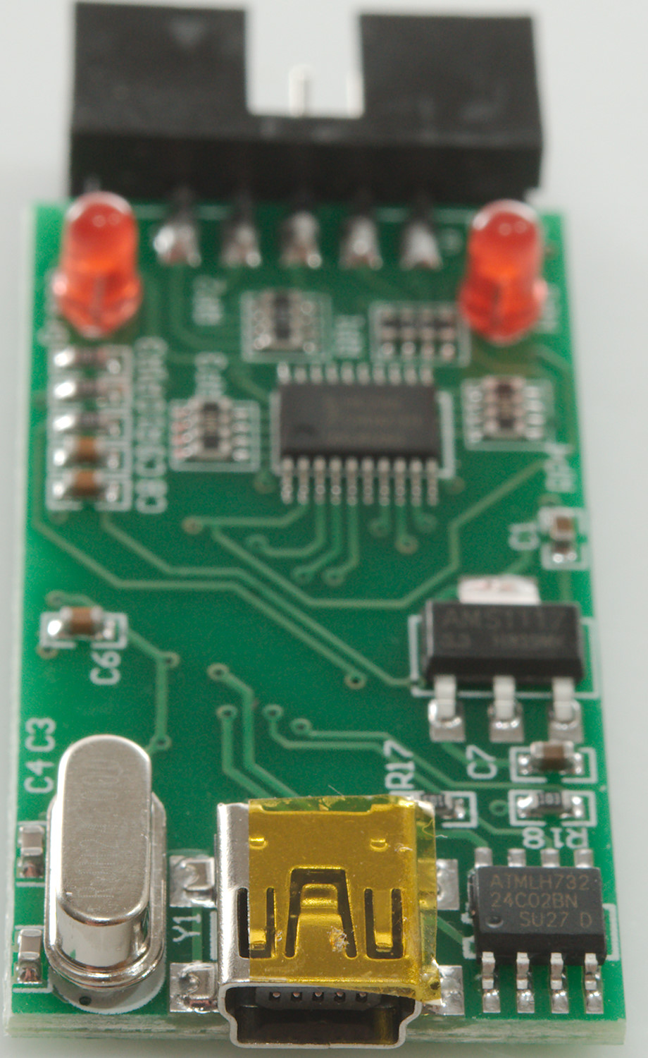
Each input has a 100 ohm resistor and a 100kOhm pull down before a HC245 buffer. There is a 3.3V regulator and a EPPROM (24C02: 256 bytes).
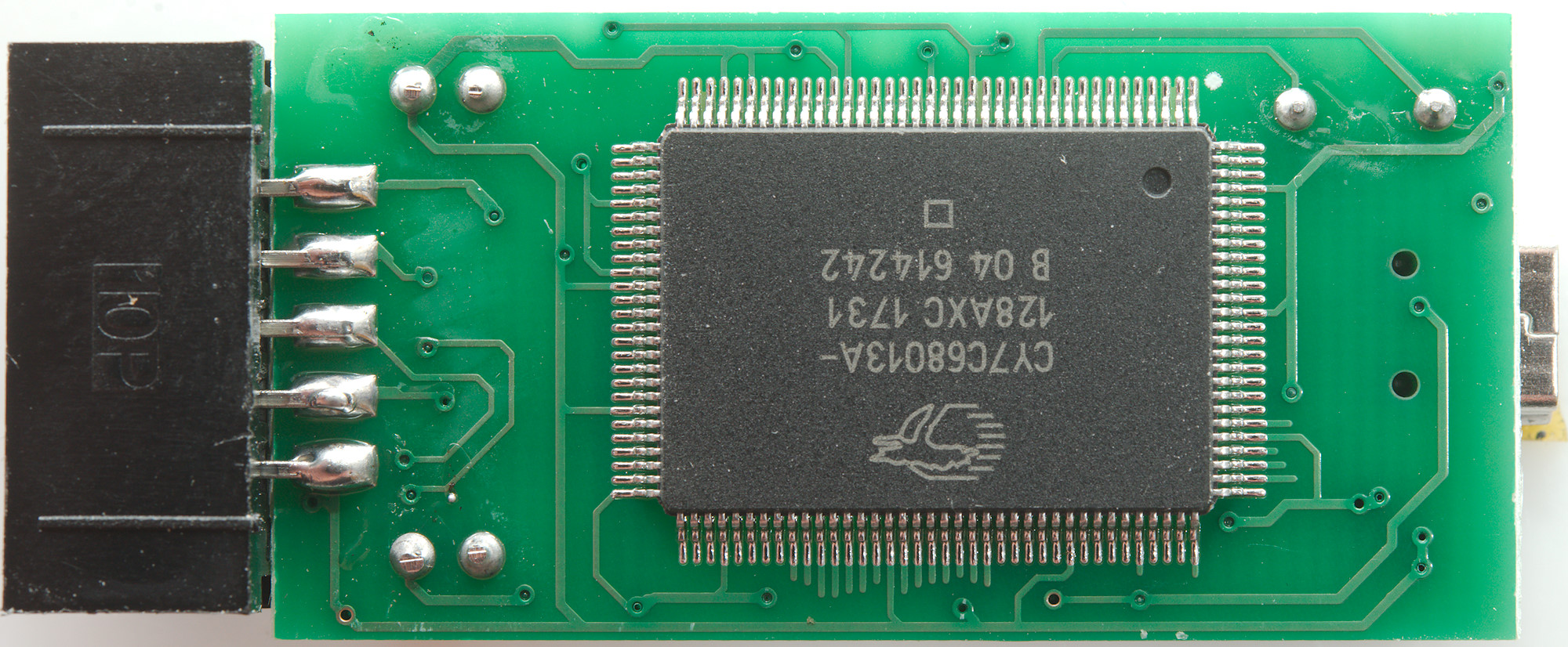
This chip basically does everything, it contains a USB interface, a 8051 processor, hardware based fifos that can stream directly to USB.
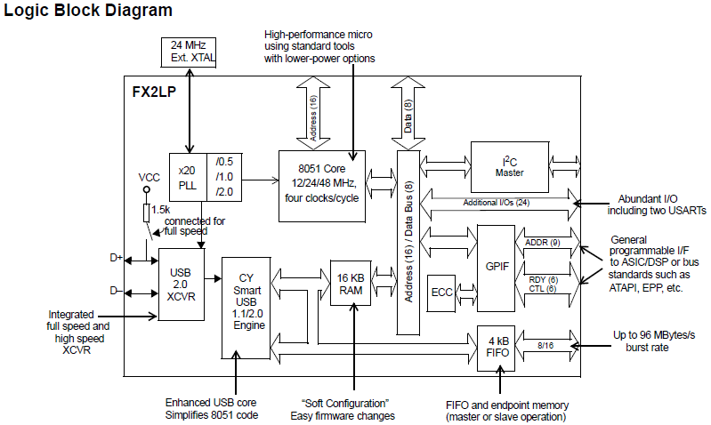
From the data sheet.

Conclusion
The logic analyzer is a nice supplement to many oscilloscopes, especially cheap models. The many decoders are way beyond what most scopes usual can do and decoders will often cost money for scopes, here they are free. The logic analyzer is not as fast as a scope and can only show two levels, this makes it fine for checking a lot of timing, but useless to check signal levels. I tested with both 3.3V and 5V logic, both worked.
Officially the maximum sample rate is 24MHz, but the software frequently locked up when I tried to use that, lower sample rates worked fine.
The software (PulseView) could use a better user interface and some grouping of the decoders (This is present in the newest beta).
This is a very good accessory when working with microprocessors, PWM, protocols, etc., but it cannot replace a scope, only supplement it.
Notes
Sigrok PulseView: Downloads - sigrok
Manual: https://sigrok.org/doc/pulseview/0.4.1/manual.pdf
Saleae Logic: Logic analyzer software from Saleae
Both pieces of software can be downloaded and tested, they will generate some simulation data.